MOLLER Spectrometer Update
650 likes | 753 Views
This document summarizes the comprehensive updates on the spectrometer design for the MOLLER (Muon-to-Electron-Rate Ratio) experiment, highlighting engineering reviews, layout adjustments, and optimization of collimators. Key aspects discussed include large phase space considerations, beam properties, cooling solutions, and the optimization of detector positions and orientations. The collaboration emphasizes ongoing efforts to refine optics, manage magnetic forces, and enhance sensitivity, all essential for achieving accurate measurements in upcoming experiments.

MOLLER Spectrometer Update
E N D
Presentation Transcript
MOLLER Spectrometer Update Juliette M. Mammei
Large Phase Space for Design • Large phase space of possible changes • Field (strength, coil position and profile) • Collimator location, orientation, size • Choice of Primary collimator • Detector location, orientation, size • Large phase space of relevant properties • Moller rate and asymmetry • Elastic ep rate and asymmetry • Inelastic rate and asymmetry • Transverse asymmetry • Neutral/other background rates/asymmetries • Ability to measure backgrounds (the uncertainty is what’s important) • Separation between Moller and ep peaks • Profile of inelastics in the various regions • Degree of cancellation of transverse (F/B rate, detector symmetry) • Time to measure asymmetry of backgrounds (not just rate) • Beam Properties (location of primary collimator) MOLLER Collaboration Meeting September 28-29, 2012
Spectrometer Design Ideal current distribution Conductor layout Optics tweaks • Fill azimuth at low radius, far downstream • Half azimuth at upstream end • No interferences • Minimum bends 5x OD of wire • Minimum 5x ms radius • Double-pancake design • Clearance for insulation, supports • Return to proposal optics or better • Optimize Moller peak • Minimize ep backgrounds • Symmetric front/back scattered mollers(transverse cancellation) • Different W distributions in different sectors (inelastics, w/ simulation) • Optimize Moller peak • Eliminate 1-bounce photons • Minimize ep backgrounds • Symmetric front/back scattered mollers (transverse cancellation) • Different W distributions in different sectors (inelastics, w/ simulation) • Force calculations • Symmetric coils • asymmetric placement of coils • Sensitivity studies • Materials • Coils in vacuum or not • Water-cooling connections • Support structure • Electrical connections • Power supplies Optimize collimators Add’l input from us Engineering design MOLLER Collaboration Meeting September 28-29, 2012
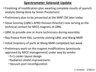
Work since the proposal • First Engineering Review • Verified the proposal map in TOSCA • Created an actual conductor layout with acceptable optics • Since the engineering review • New conductor layout, take into account keep-out zones • Water cooling more feasible • Preliminary look at the magnetic forces MOLLER Collaboration Meeting September 28-29, 2012
Work since the collaboration meeting • Purchase of a new machine and TOSCA license for use at • University of Manitoba • Interfacing with engineers • JLab engineers estimate that pressure head is not an issue • New conductor layout with larger water cooling hole “approved” • MIT engineers recalculate Robin’s initial water cooling calculations • Determine what more work is needed on our side • Ongoing/Future work • Optimization of the optics • Magnetic force studies • Sensitivity studies • Collimator optimization • Design of the water-cooling and supports • Design of electrical connections • Look at optics for 3 coils MOLLER Collaboration Meeting September 28-29, 2012
Tracks in TOSCA Mollers (blue) eps (green) Not using the mesh - “coils only” calculation fast enough on my machine - Actual layout much slower – use blocky version or improve mesh Mollers, no collimation(red) Mollers, accepted (blue) eps, accepted (green) MOLLER Collaboration Meeting September 28-29, 2012
Proposal Model to TOSCA model Home built code using a Biot-Savart calculation Optimized the amount of current in various segments (final design had 4 current returns) Integrated along lines of current, without taking into account finite conductor size “Coils-only” Biot-Savart calculation Verified proposal model Created a first version with actual coil layout Created second version with larger water cooling hole and nicer profile; obeyed keep-out zones MOLLER Collaboration Meeting September 28-29, 2012
Concept 2 – Post-review 3L 3R 4L 4C 4R • Current density not an issue, but affects cooling • Larger conductor • Larger water-cooling hole • Fewer connections • Less chance of developing a plug • New layout • Use single power supply • Keep-out zones/tolerances • Need to think about supports • Study magnetic forces • Continued simulation effort • Consider sensitivities • Re-design collimation • Power of incident radiation 2L 2R 1BL 1BR 1AL 1AR MOLLER Collaboration Meeting September 28-29, 2012
Layout 3L 3R 3L 3R 4L 4C 4R 4L 4C 4R 2L 2R 2L 2R 1BL 1BR 1BL 1BR 3L 3R 1AL 1AR 1AL 1AR 2L 2R 1BL 1BR 1AL 1AR MOLLER Collaboration Meeting September 28-29, 2012
Upstream Torus MOLLER Collaboration Meeting September 28-29, 2012
Sector Orientation MOLLER Collaboration Meeting September 28-29, 2012
Tweaking the Optics 1 (2.0) 8 (2.11) 6 (2.9) 5 (2.8) 2 (2.5) 1 (2.0) 3 (2.6) 7 (2.10) 4 (2.7) MOLLER Collaboration Meeting September 28-29, 2012
Tweaking the Optics 0 (1.0) 8 (2.11) MOLLER Collaboration Meeting September 28-29, 2012
Comparison of GEANT4 Simulations Proposal
Comparison of GEANT4 Simulations TOSCA version MOLLER Collaboration Meeting September 28-29, 2012
2.6 MOLLER Collaboration Meeting September 28-29, 2012 16
Current Version of the Hybrid and Upstream Default svn MOLLER Collaboration Meeting September 28-29, 2012 17
Tweaking the Optics Assume: 6.0-15.4 mrads from upstream end of target Finite target effects: We’ll accept some high angles from further downstream for which we won’t have full azimuthal acceptance Primary concern: focus the “good” high angles Blue: All Red: “Good” Green: “Extreme” Blue: low angles Green: mid angles Red: high angles MOLLER Collaboration Meeting September 28-29, 2012
Collimator Study • Look at focus for different • Sectors • Parts of target • Useful for optics tweaks and collimator optimization • Ideally the strips would be vertical in these (actually theta vs. radius) plots see elog 200 MOLLER Collaboration Meeting September 28-29, 2012
Rate Comparison* *Assuming 75µA MOLLER Collaboration Meeting September 28-29, 2012
Photons see elog 199 MOLLER Collaboration Meeting September 28-29, 2012
Magnetic Forces Use TOSCA to calculate magnetic forces on coils Have calculated the centering force on coil: ~3000lbs (compare to Qweak: 28000 lbs) Need to look at effects of asymmetric placement of coils Could affect the manufacturing tolerances MOLLER Collaboration Meeting September 28-29, 2012
Sensitivity Studies • Need to consider the effects of asymmetric coils, misalignments etc. on acceptance • This could affect our manufacturing tolerances and support structure • Have created field maps for a single coil misplaced by five steps in: • -1° < pitch < 1° • -4° < roll < 4° • -1° < yaw < 1° • -2 < r < 2 cm • -10 < z < 10cm • -5° < φ < 5° • Simulations need to be run and analyzed MOLLER Collaboration Meeting September 28-29, 2012
GEANT4 • Moved to GDML geometry description • Defined hybrid and upstream toroids • Parameterized in same way as the TOSCA models MOLLER Collaboration Meeting September 28-29, 2012
GEANT4 – Upstream Torus MOLLER Collaboration Meeting September 28-29, 2012
GEANT4 – Hybrid Torus MOLLER Collaboration Meeting September 28-29, 2012
GEANT4 MOLLER Collaboration Meeting September 28-29, 2012
Magnet Stats MOLLER Collaboration Meeting September 28-29, 2012
Extra Slides MOLLER Collaboration Meeting September 28-29, 2012
Water-cooling and supports Verified by MIT engineers – cooling could be accomplished in concept 2 with 4 turns per loop Still 38 connections per coil! Suggestion from engineering review: Put the magnets inside the vacuum volume MOLLER Collaboration Meeting September 28-29, 2012
GEANT4 - Collimators MOLLER Collaboration Meeting September 28-29, 2012
GEANT4 – Acceptance definition MOLLER Collaboration Meeting September 28-29, 2012
θlow,down θhigh,down Finite Target Effects θhigh,up Router θlow,up Assume 5.5 mrads at upstream end of target, instead of center Rinner ztarg,up ztarg,center ztarg,down
MOLLER Collaboration Meeting September 28-29, 2012
Direct Comparison of Fields Complicated field because of multiple current returns The average total field in a sector in bins of R vs. z The difference of the total field in a sector in bins of R vs. z for the TOSCA version of the proposal and the original proposal model MOLLER Collaboration Meeting September 28-29, 2012
Field Components MOLLER Collaboration Meeting September 28-29, 2012
Field Components MOLLER Collaboration Meeting September 28-29, 2012
Comparison of field values Red – proposal model Black – TOSCA model By (left) or Bx (right) vs. z in 5° bins in phi -25°— -20° -25°— -20° -20°— -15° -20°— -15° -15°— -10° -15°— -10° -10°— -5° -10°— -5° -5°— 0° -5°— 0° MOLLER Collaboration Meeting September 28-29, 2012
Proposal Model MOLLER Collaboration Meeting September 28-29, 2012
Actual Conductor Layout MOLLER Collaboration Meeting September 28-29, 2012
Choose constraints • Choose (standard) conductor size/layout minimizes current density • Try to use “double pancakes”; as flat as possible • Minimum bend radius 5x conductor OD • Fit within radial, angular acceptances (360°/7 and <360°/14 at larger radius) • Total current in each inner “cylinder” same as proposal model • Take into account water cooling hole, insulation • Need to consider epoxy backfill and aluminum plates/ other supports? • Radial extent depends on upstream torus and upstream parts of hybrid!! MOLLER Collaboration Meeting September 28-29, 2012
Conductor Size Need to “fill” the available space at low radius Trade-off between more insulation for smaller conductor and losing space at the “edges” with larger conductor Also need to fit all the conductor in a particular radius at a given z location • Much bigger conductors have even higher • current densities because of “edge” effects
Conductor Size Need to “fill” the available space at low radius Trade-off between more insulation for smaller conductor and losing space at the “edges” with larger conductor Also need to fit all the conductor in a particular radius at a given z location • Much bigger conductors have even higher • current densities because of “edge” effects 3C 3RA 3LA 1LC 3LB 3RB 1RC 2C 2LB 2RB 2LA 2RA 1LB 1RB 1LA 1C 1RA
Conductor Size Need to “fill” the available space at low radius Trade-off between more insulation for smaller conductor and losing space at the “edges” with larger conductor Also need to fit all the conductor in a particular radius at a given z location • Much bigger conductors have even higher • current densities because of “edge” effects 3C 3RA 3LA 1LC 3LB 3RB 1RC 2C 2LB 2RB 2LA 2RA 1LB 1RB 1LA 1C 1RA
Actual conductor layout MOLLER Collaboration Meeting September 28-29, 2012
Actual conductor layout MOLLER Collaboration Meeting September 28-29, 2012
Blocky Model superimposed MOLLER Collaboration Meeting September 28-29, 2012
Keep Out Zones ±360°/28 ±360°/14 • cones are defined using: • nothing w/in 5σ of the multiple scattering radius • + 1/4" each for Al support and W shielding MOLLER Collaboration Meeting September 28-29, 2012
Keep Out Zones ±360°/28 ±360°/14 • cones are defined using: • nothing w/in 5σ of the multiple scattering radius • + 1/4" each for Al support and W shielding MOLLER Collaboration Meeting September 28-29, 2012
Keep Out Zones ±360°/28 ±360°/14 • cones are defined using: • nothing w/in 5σ of the multiple scattering radius • + 1/4" each for Al support and W shielding MOLLER Collaboration Meeting September 28-29, 2012