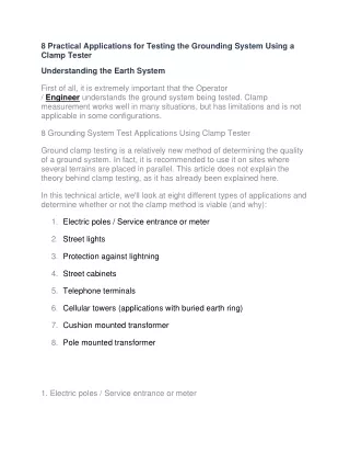
8 Practical Applications for Testing the Grounding System Using a Clamp Tester
60 likes | 62 Views
Ground clamp testing is a relatively new method of determining the quality of a ground system. In fact, it is recommended to use it on sites where several terrains are placed in parallel. This article does not explain the theory behind clamp testing, as it has already been explained here.

8 Practical Applications for Testing the Grounding System Using a Clamp Tester
E N D
Presentation Transcript
8 Practical Applications for Testing the Grounding System Using a Clamp Tester Understanding the Earth System First of all, it is extremely important that the Operator / Engineer understands the ground system being tested. Clamp measurement works well in many situations, but has limitations and is not applicable in some configurations. 8 Grounding System Test Applications Using Clamp Tester Ground clamp testing is a relatively new method of determining the quality of a ground system. In fact, it is recommended to use it on sites where several terrains are placed in parallel. This article does not explain the theory behind clamp testing, as it has already been explained here. In this technical article, we'll look at eight different types of applications and determine whether or not the clamp method is viable (and why): 1.Electric poles / Service entrance or meter 2.Street lights 3.Protection against lightning 4.Street cabinets 5.Telephone terminals 6.Cellular towers (applications with buried earth ring) 7.Cushion mounted transformer 8.Pole mounted transformer 1. Electric poles / Service entrance or meter
The more parallel grounds in series with the electrode under test, the closer the measurement is to the actual value of the resistance to ground. Utility poles are an ideal application for the clamp method. Earth systems on utility poles have many parallel ground connections, making them an ideal location to use the clamp method. Each pole has a ground electrode to maintain outage and lightning protection, and pole- mounted transformers have two electrodes on star-configured systems. It is important that these electrodes are checked. The overall earth value of such systems should generally be less than 0.3 - 0.5Ω, while each electrode typically needs to be less than 10 - 20Ω to be effective. Another related application is to test the sol-resistance of the electrodes on a service entrance or a meter (see Figure 2 below). In this case, it is possible that several earth paths, two electrodes or possibly a connection to a water pipe are connected to earth. Be sure to identify the best positions to take a measurement. Sometimes it is best to clamp the electrode itself below where the earth connections are made. 2. Public lighting Street lighting is a similar application used for the electrodes of distribution poles. The wire going to the electrode of each street light can be tightened, but remember to tighten the correct side of the ground conductor as shown in Figure 3 below. 3. Lightning protection
Another ideal application of the clamp test method is to test the ground electrodes on the lightning protection. Lightning protection on any building is only as effective as the quality of its grounding. The electrodes are normally placed at each corner of a building with additional electrodes between larger buildings. The conductors used are generally copper tapes with a maximum width of 50 mm. The following figure shows a typical lightning protection circuit where a clamp ground tester is clamped around the electrode. In many cases this is difficult because the electrode is buried in a small pit. In addition, many lightning protection strips are equipped with removable links to allow the application of a two-wire continuity test. These removable ties, often referred to as “Jug Handles,” take a long time to remove, but are ideal locations to use a clamp tester. The clamp tester will measure the entire loop, including all connections and tape links, just like a two-wire test. Many lightning protection systems on factory buildings, especially in European countries, use lightning receptors mounted at regular intervals on the roof. These receivers are all interconnected as shown in the following figure. This approach further decreases the series resistance of the parallel earth path, which means that the measured value is even closer to the actual resistance to earth of a tested electrode. Use of lightning receptors mounted at regular intervals on the roof Remember that there could be other connections to the lightning protection system. The user must remember to tighten the tape under all connections. Otherwise, the earth electrode will be tested alongside any other earth path. There may be connections to external metal structures such as metal balconies and handrails.
These should also be above the clamp tester attachment point. Remember the importance of a visual inspection as well. With the price of copper, grounding strips can be cut and stolen. Depending on where the tape is cut and how the system is tied, the instrument might return a good, but false, reading. 4. Street cabinets Another application is to test the ground electrode installed inside the primary connection points, sometimes referred to as street cabinets - flexibility points These electrodes should generally be below 25Ω to maintain reliability. In this application, there cannot be more than two parallel earth paths in series with the electrode. However, according to calculations, if the clamp ground tester provides a reading below 25Ω, then the electrode should definitely be below 25Ω. 5. Telephone terminals The telephone base ground electrodes can be tested using the clamp method. The cable sheaths are all connected to an earth bar, which is itself connected to the earth. The clamp can be placed around the cable connecting the earth bar to the electrode performing a test. If access is difficult, a temporary extension can be installed to facilitate installation on the clamp tester.
6. Cell Towers (applications with buried earth ring) A ground resistance measurement cannot be performed if the rods are connected by a ring buried under the ground. This type of setup, common in cell towers, allows access somewhere above the ring. Cellular towers are grounded at the base, with each guy wire grounded and all interconnected in a circle of patterns. If the operator clamps the head of one of the hooking wire to the ground, the test current will simply complete the circuit through the grounding ring and not through the ground. The test current flows through the conductor which connects the various elements (ground rods) making up the ring. As such, the clamp earth tester will not measure the quality of the earth system. The reading will actually be a reading of the "loop" resistance. This measurement allows the operator to check the connections under the ground. 7. Transformer on base The transformer ground electrodes mounted on the board can be checked using the clamp method. However, it sometimes happens that multiple connections are connected to the same electrode so that the user can have clamp around the electrode itself below the connections. If all of these connections are hooked up to a large buried ground sheet, then this measurement would become a continuity measurement, as the test loop would not have a ground path.
8. Pole mounted transformer Remember the golden rules of clamp testing, “there must be a loop resistance to measure”! There are cases with utility poles where this loop does not exist, at least not where you want it to. The figure below shows a system with a star-delta transformer mounted on a pole with two sets of electrodes. No set of electrodes is connected to an overhead ground cable. One is connected to the metal case of the transformer and the other to the star point of the LV secondary winding. The danger here is that the measured loop may be between the two sets of electrodes, with part of the loop being the resistance of the wooden pole, resulting in a high measurement. This could mislead the user into believing that there is a problem when there is none. In contrast, in the graphic below, there is a connection to the local distribution and its local mass system. This means that we now have a ground loop to measure and a measurement can be taken. However, remember that the resistance measurement taken is a combination of the two earths in series. A measurement of 40 Ω does not mean that each electrode system is less than 25 Ω of course, one could be 10 Ω and the other 30 Ω.If the measurement is, for example, 10Ω, then we know that everything will be fine. Burraq Engineering Solutions is providing practically electrical courses in Lahore. We offer PLC course, SOLAR SYSTEM Installation and DESIGN COURSE, ETAP course, DIALAX course, Panel FABRICATION course, VFD course, ADVANCED Course Panel, SWITCHERGEAR design course, Building Electrical design course and all electrical diploma courses in Lahore.