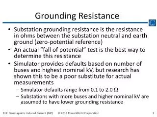
TESTING GROUNDING SYSTEMS
TESTING GROUNDING SYSTEMS. Enhanced by: Roy W. Milam Electrical Engineer/Instructor National Mine Health and Safety Academy Beckley, West Virginia. Originally Developed by: RONALD J. RENOWDEN - CMSP Denver Field Office Supervisor, MNM MSHA Rocky Mountain District Denver, Colorado.

TESTING GROUNDING SYSTEMS
E N D
Presentation Transcript
TESTING GROUNDING SYSTEMS Enhanced by: Roy W. Milam Electrical Engineer/Instructor National Mine Health and Safety Academy Beckley, West Virginia Originally Developed by: RONALD J. RENOWDEN - CMSP Denver Field Office Supervisor, MNM MSHA Rocky Mountain District Denver, Colorado
TESTING GROUNDING SYSTEMS 30 CFR §56/57.12028 As required by:
56/57.12028 the REG. “Continuity and resistance of grounding systems shall be tested immediately after installation, repair, and modification; and annually thereafter. A record of the resistance measured during the most recent test shall be made available on request by the Secretary or his duly authorized representative.”
WHY DO WE TEST ? Ensure that continuity & resistance tests are conducted on a specific schedule (at least annually) Alert mine operators if there is a problem in the grounding system Problem may not allow the circuit protective devices to quickly operate when faults occur
WHY DO WE TEST? With exception of fixed installations - Numerous fatalities and injuries have occurred due to HIGH resistance or LACK of continuity in equipmentgrounding systems Proper testing and maintenance of grounding systems can prevent electrical accidents This all sounds so good that we made it the policy regarding 12028.
56/57.12028 the POLICY The intent of this standard is to ensure that continuity and resistance tests of grounding systems are conducted on a specific schedule. These tests will alert the mine operator if a problem exists in the grounding system which may not allow the circuit protective devices to quickly operate when faults occur. With the exception of fixed installations, numerous fatalities and injuries have occurred due to high resistance or lack of continuity in equipment grounding systems. These accidents could have been prevented by proper testing and maintenance of grounding systems.
Grounding systems typically include the following: • 1.equipment grounding conductors - the conductors used to connect the metal frames or enclosures of electrical equipment to the grounding electrode conductor; • 2.grounding electrode conductors • - the conductors connecting the grounding electrode to the equipment grounding conductor; and • 3.grounding electrodes • - usually driven rods connected to each other by suitable means, buried metal, or other effective methods located at the source, to provide a low resistance earth connection. P O L I C Y
Operators shall conduct the following tests: • 1.equipment grounding conductors - continuity and resistance must be tested immediately after installation, repair, or modification, and annually if conductors are subjected to vibration, flexing or corrosive environments; • 2.grounding electrode conductors - continuity and resistance must be tested immediately after installation, repair, or modification, and annually if conductors are subjected to vibration, flexing or corrosive environments; and • 3.grounding electrodes - resistance must be tested immediately after installation, repair, or modification, and annually thereafter. P O L I C Y
56/57.12028 the POLICY Conductors in fixed installations, such as rigid conduit, armored cable, raceways, cable trays, etc., that are not subjected to vibration, flexing or corrosive environments may be examined annually by visual observation to check for damage in lieu of the annual resistance test. When operators elect to conduct this visual examination as a method of compliance with 30 CFR56/57.12028, MSHA will require that a record be maintained of the most recent annual visual examination.
56/57.12028 the POLICY • Grounding conductors in trailing cables, power cables, and cords that supply power to tools and portable or mobile equipment must be tested as prescribed in the regulation. This requirement does not apply to double insulated tools or circuits protected by ground-fault-circuit interrupters that trip at 5 milli-amperes or less.
56/57.12028 the POLICY Testing of equipment grounding conductors and grounding electrode conductors is not required if a fail-safe ground wire monitor is used to continuously monitor the grounding circuit and which will cause the circuit protective devices to operate when the grounding conductor continuity is broken.
56/57.12028 the POLICY A record of the most recent resistance tests conducted must be kept and made available to the Secretary or his authorized representative upon request. When a record of testing is required by the standard, MSHA intends that the test results be recorded in resistance value in ohms. That’s all the policy! But what does it all mean ?
TYPICAL GROUNDING SYSTEMhas three parts EQUIPMENT GROUNDING CONDUCTORS (the most important part!!!) Grounding Electrode Conductors Grounding Electrodes
EQUIPMENT GROUNDING CONDUCTOR The conductors used to connect the metal frames or enclosures of electrical equipment to the grounding electrode conductor Life Wire; Life Line Most important electrical safety item in the electrical system People protector
Equipment Grounding Conductors GROUNDING BUS maybe in MCC Motor 1 Motor 4 Motor 2 Motor 3
GROUNDING ELECTRODE CONDUCTOR Conductor that connects the grounding electrode and the transformer to the equipment grounding conductor TRANSFORMER Main Ground Bus maybe in the MCC Earth Grounding Electrode
GROUNDING ELECTRODES Usually driven rods connected to each other by suitable means, buried metal plates, or any other effective methods located at the power source to provide a low resistance earth connection. What is actually in contact with Earth. Grid Rod
EQUIPMENT GROUNDING CONDUCTORSTest for Continuity andResistance Immediately after - INSTALLATION, REPAIR, OR MODIFICATION, AND ANNUALLY, IF conductors are subjected to VIBRATION FLEXING CORROSIVE ENVIRONMENTS
GROUNDING ELECTRODE CONDUCTORTest for Continuity and Resistance Immediately after - INSTALLATION, REPAIR, OR MODIFICATION, AND ANNUALLY, IF conductors are subjected to VIBRATION FLEXING CORROSIVE ENVIRONMENTS
GROUNDING ELECTRODESTesting Test for Resistance (Earth) Immediately after - INSTALLATION, REPAIR, OR MODIFICATION, AND ANNUALLY thereafter.
Are there EXCEPTIONS? YES !!! • In lieu of doing annual resistance tests, the Groundsmay be examined annually by visual observation to check for damage….. • BUT ONLY IF: • The conductors are in fixed locations such as; • RIGID CONDUIT • ARMORED CABLE • RACEWAYS • CABLE TRAYS, ETC (there’s more)
MORE EXCEPTIONS These FIXED LOCATIONS MUST NOTbeSUBJECTED TO: Vibration FLEXING CORROSIVES
HOW MUCH IS TOO MUCH ? FLEXING VIBRATION CORROSIVES
HOW MUCH IS TOO MUCH ? The inspector makes the final determination concerning areas acceptable to visual examinations
IFVISUALEXAMS ARE CONDUCTED MSHA policy requires that a WRITTENRECORD be maintained of the most recent ANNUALVISUALEXAMINATION, can be electronic
EQUIPMENT GROUNDING CONDUCTORS IN: Trailing cables Power cables Cords supplying power to tools Cords and cables supplying power to portable or mobile equipment MUST BE TESTED AS PRESCRIBED IN THE REGULATION
When Is Testing NOT Required? IF a fail-safe ground wire monitor is used. The monitor will cause the circuit protective device to open when the grounding conductor continuityis broken. It continuously monitors the continuity of the grounding conductor. Double insulated tools are used. There is no grounding conductor to test. If the circuit used incorporates a GFCI that trips at 5 milli-amps or LESS. There are 110v and 220v devices now available.
RECORDS RESISTANCE VALUES IN OHMS Most recent tests Must be available for review by MSHA upon request No specific format required Be legible Visual exam records
A little ADVICE ? Should have electrical knowledge Know how to test and use the instrument/PPE Know what kind of electrical system Check circuit protective device vs. Ohms test Check with power off Proper size ground wire Never let metal framework or earth be the primary grounding conductor Never use peg grounding
NATIONAL ELECTRICAL CODE Section 250-51-EFFECTIVE GROUNDING PATH: The path to ground from circuits, equipment, and metal enclosures for conductors shall: Be permanent and electrically continuous Have capacity to conduct safely any fault current likely to be imposed on it, and Have sufficient low impedance to limit the voltage to ground and to facilitate the operation of the circuit protective devices. The earth SHALL NOT be used as the sole equipment grounding conductor
OK, now that the operator has tested his grounding circuit and recorded the results, what do we do with them? In other words……
How do you know if the ground wire resistance is okay? • Can apply good old OHM’S LAW: • E = IRE = VOLTSI = AMPS (current)R = RESISTANCE (ohms)EI =R E I R
BUT …..FIRST ! • Remember OHM’S LAW ! ( E = IR ) • Circuits are protected by fuses/breakers against SHORT CIRCUITS AND GROUND FAULTS • IF GF occurs, we want the fuse/breaker to clear ASAP! • Question? Where does the current go when a ground fault occurs? • GROUNDING CONDUCTOR carries the fault current back to the SOURCE (current does not return to earth, but sometimes travels thru it). • FAULT CURRENT takes path of LEAST resistance?
CONTINUED • IF ground wire is missing or high resistance, current will flow in dangerous places to return to the source. • TOUCH AND STEP POTENTIALS MAY EXIST ON THE FRAMES OF EQUIPMENT AND ON THE EARTH • HAZARDOUS!!!!! : SHOCK, BURNS, ELECTROCUTION……..DEATH
EXAMPLE: • The operator’s record of resistance testing (in OHMS) shows the following: • Crusher motor = 1 ohm • Screen Deck = .5 ohm • Stacker main motor = 1.5 ohm • Conveyor 1 = 1 ohm
Example:What’s Next ? • Need: Circuit/System VOLTAGE: • Motors supplied with 3 phase, 460 volt AC • Grounded WYE Service; Ø-Ø=460v; Ø-grd=265v • Need: Fuse/Circuit Breaker Size (for each) • 100hp, 125amps, 3-fuses @ 300amps each (crusher motor) • 40hp, 52amps, 3-fuses @ 100amps each (screen) • 25hp, 34amps, 70 amp breaker (stacker) • 10hp, 14amps, 30 amp breaker (conveyor 1)
GROUNDED WYE • Grounded WYE Service; 460 V, 3-PHASE ØA-ØB=460v; ØA-grd=265VØA-ØC=460v; ØB-grd=265VØB-ØC=460v; ØC-grd=265V O A B A O B C O C Ground Ground
How good is the equipment grounding? • CONVEYOR 1: 1ohm, Ø-grd=265v. • How much FC will flow if GF at motor frame? • To find current (ohms law) I= E/R. 265v I = =265 amp FC; On 30 amp 1ohm breaker • 265a.(FC)/30a(bkr) = 8.83...What’s this mean? • Breaker will TRIP almost instantaneous level ASAP • GOOD GROUNDING!
LET’S CHECK ANOTHER ! • SCREEN:.5 ohms,Ø-grd=265v 265v I = =530 ampFC; On 100 amp .5ohm fuses • 530a.(FC)/100a.(fu) = 5.30...What’s this mean? • Fuse will not TRIP near instantaneous level (ASAP) • GOOD GROUNDING ?Questionable! Review trip curve chart for fuse to find trip time…. • ADVICE: Check connections; loose, dirty, wire size? CORRECT/ REPAIR! Screens- flexing and vibration!
LET’S CHECK ANOTHER ! • CRUSHER: 1 ohm,Ø-grd=265v 265v I = =265 ampFC; 300 amp fuses 1ohm • 265a.(FC)/300a.(fu) = .88 ...What’s this mean? • Fuse will not BLOW (must see at least 125% to begin) • DANGEROUSGROUNDINGUNACCEPTABLE! • ADVICE: Check connections; loose, dirty, wire size? CORRECT & REPAIR!Crushers - flexing and vibration
Let’s make a small change!!! CRUSHER: 1 ohm,Ø-grd=265v, but this time we’re going to use a 100 Amp, Magnetic Trip Circuit Breaker with a trip range of 150-480 amps, set on LOW, as protection. 265v I = =265 amp FC; CB set 150 Amps 1ohm • 265a.(FC)/150a.(Inst.) = 1.77 ...What’s this mean? • Breaker will TRIP instantaneously. • GOOD GROUNDING!
Corner Grounded Delta • Corner Grounded Delta Service; 460 V, 3-PHASEØA-ØB=460v; ØA-grd=0VØA-ØC=460v; ØB-grd=460VØB-ØC=460v; ØC-grd=460V O A B O B C O C A Ground
Corner Grounded Delta • CONVEYOR 1: 1ohm, Ø-grd=480v. • How much FC will flow if GF at motor frame? • To find current (ohms law) I= E/R. 480v I = =480 ampFC; On 30 amp breaker 1ohm • 480a.(FC)/30a(bkr) = 16.0...What’s this mean? • Breaker will TRIP at instantaneous level ASAP • GOOD GROUNDING !
Corner Grounded Delta • SCREEN:.5 ohms,Ø-grd=480v480v I = .5ohm =960 ampFC; On 100 amp fuses • 960a.(FC)/100a.(fu) = 9.60...What’s this mean? • Fuse will TRIP near instantaneous level (ASAP) • GOOD GROUNDING !
Corner Grounded Delta • CRUSHER: 1 ohm,Ø-grd=480v 480v I = =480 ampFC; 300 amp fuses 1ohm • 480a.(FC)/300a.(fu) = 1.6 ...What’s this mean? • Fuse will start heating up. (must see at least 125% to begin) Will blow on very long delay. • DANGEROUS GROUNDINGUNACCEPTABLE! • ADVICE: Check connections; loose, dirty, wire size? CORRECT & REPAIR!Crushers - flexing and vibration
FLOATING or UNGROUNDED SYSTEMS BE AWARE! HAZARDOUS- IF NOT MONITORED FOR GROUNDS AND MAINTAINED ELECTRICAL SHOCK THERMAL ARC FLASH BURNS ELECTROCUTION FIRES
Now let’s look at some of the test instruments that can be used to test the grounding system
This is a Biddle Earth Tester that is battery powered. It uses 6 “C” cells. It is used to test the grounding electrode resistance.
This a type of Biddle Earth Tester that is battery powered. It is powered by 4 “C” cells. It is used to test the grounding electrode resistance. Measuring the resistance of the equipment grounding conductor for this piece of equipment.