Download

1 / 17
170 likes | 336 Views
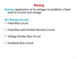
Supply Voltage Biasing in Synopsys. Andy Whetzel University of Virginia. Agenda. Quick Background FinFET technology Motivation Supply-Biased D esign Proof-of-Concept Results Challenge in Synopsys Proposed Flow Tools Custom Designer SiliconSmart Milkyway Library Compiler

E N D
Supply Voltage Biasing in Synopsys Andy Whetzel University of Virginia
Agenda • Quick Background • FinFET technology • Motivation • Supply-BiasedDesign • Proof-of-Concept Results • Challenge in Synopsys • Proposed Flow • Tools • Custom Designer • SiliconSmart • Milkyway • Library Compiler • Progress & Future Work
Background FinFET Technology • Scalable • Higher drive strength per unit silicon Image from: http://www.ece.uc.edu/~kroenker/Research/Research%20Project%20Summaries/FINFET_image004.jpg Image from: http://www.siliconsemiconductor.net/images/news/image-76523-2012-12-12.jpg
Motivation Body biasing does not work on FinFETs • MOSFET vs. FinFET: https://www.semiwiki.com/forum/content/attachments/5665d1355855218-planar-vs.-3d-finfet.jpg
Ring Oscillator • 11 Inverters • Swept bias voltage from -0.1 V to 0.1 V • 1.1 V nominal • Measured frequency, active power, and static power vs. bias voltage
Problem with Synopsys • Synopsys cannot correctly connect supply-biased gates (high output to NMOS, low output to PMOS). • Characterizing the gates is difficult because many vectors are not possible. • These gates can be viewed as similar to differential signaling. • We have found that Synopsys does not readily support this.
Proposed Flow 1. Create Schematics and Layout of Standard Cells and Supply-Biased Cells in Custom Designer 2. Characterize Standard Cells using Synopsys SiliconSmart 3. Convert Output of SiliconSmart to Binary using Library Compiler 4. Synthesize Block in Design Compiler using Standard Cell (Non-Biased) Library 6. Manipulate Netlist Generated from Design Compiler to Implement Supply-Biased Cells in ICC 5. Export Layout from Custom Designer and Import into Milkyway Environment
Custom Designer • Standard Schematic and Layout Editing • Netlist from Schematic • GDS, LEF, DEF, etc. from Layout View
SiliconSmart • Inputs to SiliconSmart (when starting from scratch): • Spice netlist • Instance files with ports and cell function • Sometimes SiliconSmart can recognize a cell’s function from its netlist, but it’s always a good idea to ensure that it is correct. • Configure.tcl file, which includes: • Operating conditions • Model namesand files • Simulator setup information • Outputs from SiliconSmart: • Liberty file with timing and power information (.lib format, human readable)
Library Compiler • Should be extension of SiliconSmart in my opinion • Converts .lib files to .db (binary) which can be read and used by Synopsys tools • We use these .db files for Design Compiler and ICC in this flow
Milkyway Environment • Import LEF file from Custom Designer for both the standard “reference” library and supply-biased library • This creates CEL and FRAM views for use in ICC
Tool-Specific Challenges • SiliconSmart: • It is difficult to define a supply-biased cell’s function because the inputs and outputs have different logic high and low values. Many vectors are disallowed (different logic values of high and low input) but SiliconSmart will still test these vectors unless told not to. • We have two supplies from which to measure leakage and switching power for each input. • Characterizing sequential cells is difficult because of timing issues. • Design Compiler • Will not recognize “high” and “low” (shifted up and shifted down) inputs and outputs. • Does not support differential signaling. • IC Compiler • We now need power straps for 4 supplies • Arranging layouts is more challenging
Progress • Schematics and layout complete in Custom Designer. • Standard non-biased cells are characterized. • CEL and FRAM view of both biased and non-biased cells. • Seems to be some trouble with pin extraction, ICC won’t recognize pins • Synthesized FFT in Design Compiler using non-biased cells.
Future Work • Characterize supply-biased cells. • Figure out how to extract pin information correctly. • Optimized layout for supply-biased cells. • Characterize supply-biased cells under 3 conditions: no bias, forward bias, and reverse bias. • Adjust netlist to use supply-biased cells, complete layout of supply-biased FFT.