Download
1 / 35
840 likes | 3.08k Views
Biasing. Biasing: Application of dc voltages to establish a fixed level of current and voltage. BJT Biasing Circuits: Fixed Bias Circuit Fixed Bias with Emitter Resistor Circuit Voltage-Divider Bias Circuit Feedback Bias Circuit. Fixed Bias Circuit. This is a Common Emitter

E N D
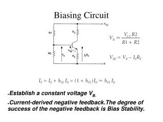
Biasing Biasing: Application of dc voltages to establish a fixed level of current and voltage. BJT Biasing Circuits: • Fixed Bias Circuit • Fixed Bias with Emitter Resistor Circuit • Voltage-Divider Bias Circuit • Feedback Bias Circuit
Fixed Bias Circuit • This is a Common Emitter (CE) configuration. • Solve the circuit using KVL. • 1st step: Locate capacitors and replace them with an open circuit • 2nd step: Locate 2 main loops which are • BE loop • CE loop
Fixed Biased Circuit • 1st step: Locate capacitors and replace them with an open circuit
Fixed Biased Circuit • 2nd step: Locate 2 main loops. BE Loop CE Loop 1 1 2 2
Fixed Biased Circuit • BE Loop Analysis: From KVL: IB Solving for IB 1 (1)
Fixed Biased Circuit From KVL: • CE Loop Analysis: IC As we know IC = dcIB Substituting IB from equation (1) VCE = VC In addition, since VBE = VB - VE 2 Also note that VCE = VC - VE Since VE = 0 VBE = VB But VE = 0
Fixed Biased Circuit • DISADVANTAGE • Unstable – because it is too dependent on β and produce width change of Q-point • For improved bias stability , add emitter resistor to dc bias.
Example 1: Determine the Following for the given Fixed Biased Circuit. • IBQ and ICQ (b) VCEQ (c) VBC Solution:
Example 2: For the given fixed bias circuit, determine IBQ, ICQ, VCEQ, VC, VB and VE. Solution:
Example 3: Given the information appearing in the Fig. (a) , determine IC, RC, RB, and VCE. Solution:IC = 3.2 mA, RC = 1.875k, RB = 282.5 k, VCE = 6 V. Example 4: Given the information appearing in Fig. (b), determine IC, VCC, and RB. Solution: IC = 3.98 mA, VCC = 15.96 V, = 199, RB = 763 k. Fig. (a) Fig. (b)
Load line Analysis with Fixed Bias Circuit DC load line is drawn by using the following equations: VCE = VCC
Load line Analysis with Fixed Bias Circuit Effect of Varying IB on the Q-Point:
Load line Analysis with Fixed Bias Circuit Effect of varying VCC on the Q-Point:
Load line Analysis with Fixed Bias Circuit Effect of varying RC on the Q-Point:
Example: Given the load line and the defined Q-point , determine the required values of VCC, RC, and RB for a fixed bias configuration. Solution: VCE = VCC = 20 V
Emitter-Stabilized Bias Circuit • An emitter resistor, RE is added to improve stability • Solve the circuit using KVL. • 1st step: Locate capacitors and replace them with an open circuit • 2nd step: Locate 2 main loops which; • BE loop • CE loop Resistor RE added
Emitter-Stabilized Bias Circuit • 1st Step: Locate capacitors and replace them with an open circuit.
Emitter-Stabilized Bias Circuit • 2nd Step: Locate two main loops 2 1 1 2
Emitter-Stabilized Bias Circuit BE Loop Analysis: Using KVL: Recall that IE = ( + 1)IB 1
Emitter-Stabilized Bias Circuit CE Loop Analysis: From KVL: Substituting IE IC we get 2
Example: For the given emitter bias network, determine IB, IC, VCE, VC, VE, VB and VBC. Solution:
Load line Analysis for Emitter Stabilized Bias Circuit The collector-emitter loop equation that defines the load line is: Choosing IC = 0 gives And choosing VCE = 0 gives
Example: For the given emitter stabilized bias circuit, determine IBQ, ICQ, VCEQ, VC, VB, VE. Solution:
Voltage Divider Bias • Provides good Q-point stability with a single polarity supply voltage • Solve the circuit using KVL • 1st step: Locate capacitors and replace them with an open circuit • 2nd step: Simplify circuit using Thevenin Theorem • 3rd step: Locate 2 main loops which; • BE loop • CE loop
Voltage Divider Bias • 1st step: Locate capacitors and replace them with an open circuit
Voltage Divider Rule 2nd step: Simplify the circuit using Thevenin Theorem From Thevenin’s Theorem
Voltage Divider Bias 3rd step: Locate 2 main loops. BE Loop CE Loop 1 1 2 2
Voltage Divider Bias BE Loop Analysis: From KVL: But 1
Voltage Divider Bias CE Loop Analysis: From KVL: Assume IC IE 2
DC load line with Voltage Divider Bias The dc load line can be drawn from the following equation: IC VCE VCC
Example: Determine the dc bias voltage VCE and the current IC for the given voltage divider configuration. Solution:
DC Bias with Voltage Feedback Using KVL: In this circuit, IB is assumed to be very small and I’C IC = IC. The above Equation may therefore be Re-written as BE Loop
DC Bias with Voltage Feedback Since I’C IC and IC IE, we have CE Loop
Example: Determine the quiescent level of ICQ and VCEQ for the given network. Solution: