Download
1 / 17
170 likes | 332 Views
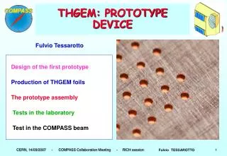
THGEM report. Second part: starting since Mai; first part includes the period between January 2008 - April 2008. Elena Rocco. Induction and Drift scans summary for THGEM without rim. INDUCTION SCAN. DRIFT SCAN. ∆V=1.475 KV. ∆V=1.475 KV. ∆V=1.45 KV. ∆V=1.45 KV. ∆V=1.35 KV. ∆V=1.35 KV.

E N D
THGEM report Second part: starting since Mai; first part includes the period between January 2008 - April 2008. Elena Rocco
Induction and Drift scans summary for THGEM without rim INDUCTION SCAN DRIFT SCAN ∆V=1.475 KV ∆V=1.475 KV ∆V=1.45 KV ∆V=1.45 KV ∆V=1.35 KV ∆V=1.35 KV The fields conditions are the same for all measurements*: Einduction=3 KV/cm, Edrift=1.5KV/cm and e collimated X-Ray source (diam=1mm) has been used with a rate about 1.7 KHz/mm2. *for the treated THGEM the Edrift was 2 KV/cm .
Gain overview (Except for the THGEM with the asymm. rim) ∆V=1.8 KV, G~5580 ∆V=1.775 KV, G~4170 ∆V=1.75 KV, G~2800 ∆V=1.5 KV, G~2500 ∆V=1.49 KV, G~2060 ∆V=1.725 KV, G~1880 ∆V=1.475 KV, G~1550 ∆V=1.475 KV, G~1510 ∆V=1.7 KV, G~1350 ∆V=1.45 KV, G~940 ∆V=1.465 KV, G~1250 ∆V=1.675 KV, G~860 ∆V=1.44 KV, G~790 ∆V=1.425 KV, G~600 ∆V=1.415 KV, G~490 ∆V=1.4 KV, G~390 ∆V=1.35 KV, G~300 ∆V=1.325 KV, G~205 ∆V=1.375 KV, G~220 ∆V=1.3 KV, G~145 The gain of the electro-chem. polished THGEM is overlapped by the gain of the kapton THGEM 3
Time stability measurements ∆V=1.775 KV Remarks: the drift field is not optimized for these meas. ∆V=1.49 KV ∆V=1.35 KV ∆V=1.45 KV Same working conditions: Einduction=3.5 KV/cm Edrift=1.5KV/cm; rate ~0.7-0.8 KHz collimated source
More about the THGEM in Kapton • Material structure; • Drift scan measuring the currents on all the electrodes.
Description of the structure of the THGEM made of Kapton SheldhallG2300 17/50* LF 110, Dupont 50 μm LF 110, Dupont 50 μm Directions of the cross sections LF 111, Dupont Sheldhall G2500 17/50* Copper Polyimide: Apical, AV, Kareka Section 1 Section 4 Kapton H, Dupont Epoxy acrylic *17/50 means 17 μm of copper and 50 μm of kapton
Drift scan measuring the currents on the THGEM made of Kapton DRIFT 6.5 mm THGEM Currents measured on all the electrodes (anode, bottom THGEM, top THGEM, drift). The sensitivity for each devices used to read out the current is ± 1nA. 5mm Top side ANODE Bottom side Configuration inside the chamber
The THGEM scheme on the “plaque” Varying the diameter, Fixed pitch d=0.5mm 8 d=0.5mm 7 9 d=0.5mm Fixed diameter, Varying the difference pitch&diameter p=0.9mm p=0.8mm p=0.7mm 4 5 6 d=0.4mm d=0.4mm d=0.4mm p=0.7mm p=0.8mm p=0.6mm 2 3 1 d=0.3mm d=0.3mm d=0.3mm p=0.5mm p=0.7mm p=0.6mm Fig.2 .THGEMs labelling. Fig.3 .THGEMs geometry for fixed thickness and cleaning. In the increasing diameter direction there’s a correspondent increasing of the breakdown voltage
Some pictures for looking in details the hole edges G10_1_sideA G10_G_sideA G10_1_sideB G10_G_sideB
Measurements planned and characterization procedure Characterisation procedure: • Kept in the oven for 24h; • Measurements of the maximum voltage applied to the THGEM in Ar/CO2 (70/30); • Switching on voltage and setup of the electronics setting irradiating the chamber; • Time stability measurement for a night (~12 h); • Quick characterisation: induction & drift scans, voltage scans, currents measurements (for gain estimation too). 8 7 9 4 5 6 Pitch constant: p=0.7 mm 2 3 1 Rim constant: d=0.3 mm directions of THGEMs characterization Voltage conditions: the idea is to keep the same voltage for all THGEMs.
G10 – sample #2 Side A Side B GEOMETRICAL CONFIGURATION DRIFT • PARAMETERS: • Diameter = 0.3 mm • Pitch= 0.6 mm • Thickness = 0.6 mm • Rim = 0 mm • Gas: Ar/CO2 – 70/30 6.5 mm THGEM Thickness 5mm ANODE
Induction Scan ∆V=1.77 KV collimated source rate~1.6 KHz/mm2 Same curve Drift field optimized ED=1.5 KV/cm Drift field not optimized ED=1.5 KV/cm Comparison between the pulse height measurement and the current measurement* *For current measurement I used different rate
Drift scans ∆V=1.77 KV collimated source rate~1.6 KHz/mm2 ∆V=1.77 KV collimated source rate~1.6 KHz/mm2 Same curve Comparison between the pulse height measurement and the current measurement* *For current measurement I used different rate
Gain estimation from current measurement REMARKS: @ the same voltage there’s almost the same gain but different geometry!!! ∆V=1.77 KV G~3420 ∆V=1.675 KV G~620
Currents behaviour Drift Scan Induction Scan
Time Stability Measurement Problems with the fit due to the low statistics for the first quick acquisition Good statistics Bad statistics V=1.77KV, Einduction=3.5 KV/cm, Edrift=1.5 KV/cm (not optimized), rate=0.8 KHz, collimated source