Download
1 / 27
270 likes | 283 Views
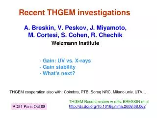
Recent THGEM investigations. Gain: UV vs. X-rays - Gain stability What’s next?. A. Breskin, V. Peskov, J. Miyamoto, M. Cortesi, S. Cohen, R. Chechik Weizmann Institute. THGEM cooperation also with: Coimbra, PTB, Soreq NRC, Milano univ, UTA…. THGEM Recent review w refs: BRESKIN et al

E N D
Recent THGEM investigations • Gain: UV vs. X-rays- Gain stability • What’s next? A. Breskin, V. Peskov, J. Miyamoto, M. Cortesi, S. Cohen, R. Chechik Weizmann Institute THGEM cooperation also with: Coimbra, PTB, Soreq NRC, Milano univ, UTA… THGEM Recent review w refs: BRESKIN et al http://dx.doi.org/10.1016/j.nima.2008.08.062 RD51 Paris Oct 08
photons Gy/h mm mm Among current applications: 2-phase LXe detectors for rare events Medical: LXe Gamma camera Also: Calorimetry LXe Gas photomultipliers N-detectors n elemental radiography Pos-sens n-dosimetry - BNCT
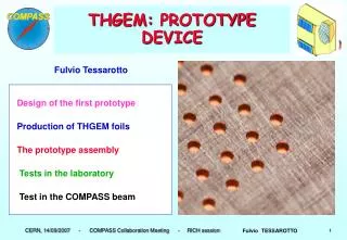
THGEM ThickGas Electron Multiplier (THGEM) THGEM 1e- in 0.5mm holes holes drilled in thick G-10 E 104-105e-s out • SIMPLE, ROBUST, LARGE-AREA • Intensive R&D • Many applications Double-THGEM: 10-100 higher gains Robust Single-photon sensitivity Effective single-photon detection 8ns RMS time resolution Sub-mm position resolution >MHz/mm2 rate capability Cryogenic operation: OK
Gain: UV vs X-rays To clarify: “are WIS previous results of “higher gain with UV compared to x-rays” - OK? Method: compare both UV and x-rays with the same detector in a single experiment
Single- & double-THGEM with UV (recall) Shalem et al NIM A558(2006)475 0.8mm thick 0.4mm thick 104 104 104 • Gain 2-THGEM / 1-THGEM ~100 • Gain 2-THGEM: function of Etrans • 2-THGEM: lower Vhole • 1-THGEM: low thickness-effect on gain: • gain0.8mm/gain0.4mm~2
Double-THGEM with 6 keV x-rays (recall) 104 Cortesi et al 2007 JINST 2 P09002
New measurements: Experimental set up pA Gas in pA TGEM -Vtop CsI To pump Am (for gain calibration) Gas out 2cm Mesh -Vdr Window THGEM geometry: Holes dia: 0.5 mm Pitch: 1 mm Thickness: 0.8 mm Rim: 0.1mm UV light 55Fe Hg lamp
Single-THGEM : Ar+5%CH4 UV Current-mode NEW WIS old pulse-mode 55Fe NEW Pulse-mode (~1kHz) Cu X-ray gun, current-mode Maximal gains with UV are 100 times higher than with X-rays. For UV and x-ray gun: The current in the plateau region (500-750V) was the same: 0.1nA. The maximum current in gain measurements was always kept below 0.5nA 104 THGEM geometry: Holes dia: 0.5 mm Pitch: 1 mm Thickness: 0.8 mm Rim: 0.1mm
Single-THGEM: Ne 104 UV, current-mode 104 55Fe Pulse-mode THGEM geometry: Holes dia: 0.5 mm Pitch: 1 mm Thickness: 0.8 mm Rim: 0.1mm The maximum gains with x-rays in Ne are higher than in Ar+5%CH4. In Ne breakdown voltages with UV and X-rays are closer.
104 104 UV Current-mode 55Fe Pulse-mode Single-THGEM: Ne + CH4 THGEM geometry: Holes dia: 0.5 mm Pitch: 1 mm Thickness: 0.8 mm Rim: 0.1mm UV Current-mode 104 55Fe Pulse-mode 104 Same as with Ne: maximum gains with x-rays in Ne+CH4 are higher than in Ar+5%CH4 and breakdown voltages with UV and X-rays are close.
Raether limit: established in large-gap avalanche detectors but valid for MPGDs (Ivanchenkov NIM A 1999), though may be different • A*n0=106-107 electrons • where A is the maximum achievable gain, n0-number of primary electrons deposited by the • radiation in the drift region • X-rays: different gain compared to UV • - In Ne/CH4 Raether limit possibly differs from Ar/CH4due to ~ 5-fold longer range of 55Fe photoelectrons (~1mm), resulting in lower ioinization density per “hole”. A possible interpretation (Peskov) To verify with alphas, hadronic beams etc
THGEM Long-term stability: recall ST PC 1mm i Gain R. Chechik SNIC2006, http://www.slac.stanford.edu/econf/C0604032/papers/0025.PDF 104 • Insulator Charging up • Hole&rim:few hours of stabilization • (gain variation ~ factor 2.) • Stabilization time function of: • Total gain (potentials) • Counting rate (current) • Material & hole-geometry (dia.,rim) • Production method • Gas & purity (e.g. moisture) Ar/5%CH4 UV, 5x10⁵ e-/mm2
Stability with UV: new data Single-THGEM geometry: Holes dia: 0.5 mm Pitch: 1 mm Thickness: 0.8 mm Rim: 0.1mm Ar/5%CH4 – flow mode Charge-up: gain dependent
2nd THGEM 1st THGEM Anode Mesh Drift mesh 9.6 mm 1.6 mm 1.6 mm THGEM GAIN STABILITY – X-RAYS Vary the distance To change the rate Fe-55 source collimated by a 3 mm dia hole THGEM geometry Material FR-4 Thickness 0.4 mm Hole size 0.6 mm Pitch 1.0 mm Rim size 0.1 mm E_drift = 100 V/cm E_transfer 1 kV/cm E_inducion= 4 kV/cm
SETUP Heated Baraton Gauge for pressure monitoring (4Torr change in 24h) Pure argon gas in UHV vessel ThGEM Temperature sensor placed on the chamber surface (0.8C in 48h) Hamamatsu PMT for photon counting Collimated X-rays Anode signal Gas can: - Flow - Circulate via getter Gas out RGA 200 gas analyzer for purity check Charge Amp+Shaper+MCA for pulse height analysis Gain corrected for pressure-changes; T-changes negligible
GAIN VARIATION vs RATE I • For a very short-term scales (<1 hr), the drop in gain is faster for higher rates • The magnitude of drop function of rate 7Hz/mm2 Gain 2000 30Hz/mm2 120Hz/mm2 300Hz/mm2 X-RAYS Argon, 770 Torr
GAIN VARIATION vs RATE II Stability reached after ~ 5h for gains ~1400 for 7-300Hz/mm2 7Hz/mm2 Gain 2000 Data normalized to pressure=770 Torr 300Hz/mm2 X-RAYS Argon, 770 Torr
GAIN VARIATION vs RATE – higher gain vs rate • At higher rate, after initial drop, the gain keeps rising while at lower rate the gain stabilizes at low value. • 2. At higher rate the detector occasionally discharges, whereas at lower rate the detector is rather stable • 3. Gain recovery after a discharge is faster at higher rates. Gain 10,000 At high rate continuous sparks begin when the gain recovered sufficiently Spark followed by slow recovery (low rate) Sparks followed by quick recovery (high rate)
GAIN VARIATION vs RATE – lower gain vs rate Lower gain: rates 7 Hz/mm2 & 70 Hz/mm2 1. At higher rate, the initial drop is shaper 2. At higher rate, after the sharp drop the gain tends to reach faster the stability observed for the lower rate. 3. The stabilization time is longer for low gain & higher rates. Gain 500
Summary of charge up in pure Ar • At low rates: gain drops to a certain level and remains constant regardless of initial gain (500-10,000) • 2. At higher rates: gain sharply drops to its minimum. The magnitude of the drop is the largest at high gain. After reaching minimum, the gain tends to recover to the value reached at low-rates. The recovery is faster at the higher gains. • 3. At high rate and high gain the gain recovery did not reach stable level – discharges due probably Raether limit in Ar.
GAIN STABILITY: rim/no-rim TRIESTE RESULTS Long time GAIN variation RIM: 0.1 mm Single THGEM, th. 0.4, Ø 0.4, p. 0.8 RIM: 0 Short time GAIN variation TRIESTE Results RIM: 0 RIM: 0.1 mm irradiation after ~10 hour at nominal voltage without irradiation irradiation at HV switch on (after ~1 day with no voltage) Remark: Comparison at diff gains Fulvio TESSAROTTO
Gain variation studies in different conditionsTRIESTE results For first series of “Eltos” pieces (with th. 0.4, diam. 0.4, pitch 0.8), Ar/CO2 70/30 and 55Fe source (~ 600 Hz), in Trieste, first 12 h: 100 μm chem. rim increase of ~ 400% 50 μm mech. rim still to be processed: large decrease 25 μm chem. rim decrease of ~ 70% 10 μm chem. rim decrease of ~ 50% (“global etching”) no rim decrease of < 30% The time to reach stabilization is shorter for smaller rims CsI deposited on pieces with 100 μm rim and with no rim: gain variations with photons ~ similar to those seen with X rays ? Fulvio TESSAROTTO
THGEM-GPM for LXe Gamma Camera Subatech-Nantes/Weizmann THGEM CsI photocathode LXe conversion volume Segmented Anode IN CONSTRUCTION LXe/GPM Tests: Jan 09 MgF2 window
300x300 THGEM THGEM geometry: Hole dia.: 0.5 mm Pitch: 1 mm Thickness: 0.4 mm (Cu~ 35 mic) Rim: 0.05 mm (can be smaller) Chemical etching/no mask Ni/Au plating Producer: Print Electronics www.print-e.co.il
SUMMARY ● In Ar+5%CH4 the maximum achievable gains measured with UV-light (~106) are ~100-fold higher than with 55Fe (~104) ● Probable explanation is the Raether limit ● In Ne and Ne-CH4 (5-23%) mixtures, under gas flushing, the maximum gains with UV and 55Fe are closer (105 - 106) ● Possibleexplanation: 55Fe photoelectron-tracks are longer in Ne and its mixtures lower density of ionization per hole lower max. gain-difference caused by charge-density effects. ● In pure Ne scintillation prevents high gains & “masks” p.e. extraction quencher ● For RICH: optimal would be Ne–based mixtures ● Quencher additives to be optimized – for high gain and efficient p.e. extraction. ● Preliminary results indicate upon ~70% extraction efficiency in Ne/23%CH4 similar to Ar/5%CH4. ●Charge-up: geometry (rim), gain and rate dependent. ● It seems that rimless holes are advantageous, but need to establish detectors’ parameters (eff QE, e-transfer photon detection efficiency) with the right conditions and gas ● Need to compare stability of LARGE-AREA rim/rimless THGEMs with UV photons ● Tests in RICH mode? Who? When? – Trieste ordered 60x60 cm THGEMs. ● 30x30cm THGEM tests: tested end 2008 at WIS ● Expected results in Cryo-THGEMs Gas Photomultipliers/LXe: early 2009.