Download

1 / 10
100 likes | 185 Views
THGEM TESTS @ CERN. September 2008 Freiburg Team Torino Team Trieste Team. Outline:. Setup description (prototypes, electronics, sources); “Small chamber” and “medium chamber”: gain characterization; Electronics tests with MAD4 and CMAD; Conclusions. Used setup (1/2).

E N D
THGEM TESTS @ CERN September 2008 Freiburg Team Torino Team Trieste Team
Outline: • Setup description (prototypes, electronics, sources); • “Small chamber” and “medium chamber”: gain characterization; • Electronics tests with MAD4 and CMAD; • Conclusions. Elena Rocco
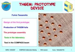
Used setup (1/2) Front End and cooling • 2 55Fe sources available with 2 different intensities; • 3 THGEM prototypes (see table below); • Bottle of gas premixed: Ar/CO2 70/30 %; • Cooling for the electronics provided; • Electronics in loco and event builder (pccofe03) available for running the acquisition independently from the main COMPASS DAQ. Medium chamber Elena Rocco Geometrical parameters and labels of the THGEM prototypes used
Used setup: electrical schemefor the small chamber (2/2) POWER SUPPLY DRIFT drift R=500 M 100 pF Edrift POWER SUPPLY THGEM 1 TOP 1 Etransfer THGEM 2 R=500 M Einduction 100 pF anode R=6 G CONFIGURATION INSIDE THE CHAMBER BOTTOM 1 R=8 G For the medium chamber the resistors in the electrical scheme are different values due to the different amplitude (charge) of the signal. For the triple THGEM is completely different POWER SUPPLY TOP 2 R=500 M 100 pF R=5.5 G BOTTOM 2 R=2.5 G Elena Rocco
Gain Characterization for the small chamber Drift field kept fixed: Edrift1.6 kV/cm • Weaker Iron source has been used for this gain characterization); • Rate few Hz; • Readout from the anode (CREMAT pre+amplifier) Signal from the anode Elena Rocco
Gain Characterization for the medium chamber • Performing this gain characterization the transfer field was changing slightly by applying different voltage to THGEM 2; • 55 Fe source used (the weaker one); • Rate 50 Hz; • Readout from the anode (CREMAT pre+amplifier) Drift field kept fixed: Edrift=0.22 kV/cm MEDIUM CHAMBER Coincidences: BOTTOM2 , PM1, PM2 Elena Rocco
Triple THGEM signal Rate 145 Hz Reading out form the anode Gain estimation using the CREMAT amplifier Elena Rocco
Electronics Tests (1/2) The gain in the chip CMAD can be programmed; The gain range is from 4.8 mV/fC to 0.4 mV/fC in discrete steps ; The granularity is 0.45 mV/digit; The range of the threshold is divided in 1024 digit, but we are using just half: from 650 digit (a little bit above the noise level) to 0 digit (the higher threshold attainable). • Concerning the CMAD : • The pedestal was optimized (650 digit), but not the noise. • Concerning the MAD4 : • A common threshold above the noise has been put (40 digits).Remind: the gain in the MAD4 is fixed, the digit range is smaller and the granularity is double respect the CMAD (0.9 mV/digit(?)) Elena Rocco
Electronics Tests (2/2) • The tuning of the electronics is not perfect because there’s some noise coming from some MAD chip. • Later on, after a fine tuning of the electronics, the scan in gain and in threshold have been performed. • A check in amplitude values of the signal has been done between the measured value and the calculated value from the whole electronics chain. Time peak acquired from our DAQ Elena Rocco
Conclusions (quite preliminary): • The prototypes can provide stable and reproducible signals, from the amplitude point of view; • The electronics chain is ready to be used and is suitable for reading out the signal from the detectors with the THGEMs; • The loading files are ready for changing the thresholds in the whole electronics (MAD and DREISAM) and for further noise studies. • For the near future: • Geometry is still to be chosen (further characterizations should be done); • tests with different gases; • Run using the cosmic rays could be taken because the setup is ready (medium chamber). Elena Rocco