Download
1 / 18
180 likes | 307 Views
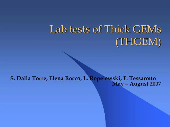
Lab tests of Thick GEMs (THGEM). S. Dalla Torre, Elena Rocco , L. Ropelewski, F. Tessarotto May – August 2007. Outline:. Geometry of the THGEM tested; Sources & Setup; First discouraging results; Different geometry and encouraging results; The rim effect; Conclusions. Ions.

E N D
Lab tests of Thick GEMs (THGEM) S. Dalla Torre, Elena Rocco, L. Ropelewski, F. Tessarotto May – August 2007
Outline: • Geometry of the THGEM tested; • Sources & Setup; • First discouraging results; • Different geometry and encouraging results; • The rim effect; • Conclusions.
Ions 40 % 60 % Electrons GEM Principle 5 µm 50 µm 55 µm 70 µm GEM hole cross section Avalanche simulation
Some THGEM pictures W2: D=0.3 mm Pitch=0.7 mm Rim=0.1 mm Thick=0.4mm R3: D=0.2 mm Pitch=0.5 mm Rim=0.01 mm Thick=0.2mm R3 W2 P1: D=0.8 mm Pitch=2 mm Rim=0.04 mm Thick=1mm R3 section P1
Sources & Parameters of the THGEMs used *Except for the Pi geometry we always used 30/70 CO2/Ar gas mixture !!
DRIFT d_drift THGEM d_ind ANODE Structure of the chamber used for testing GAS INLET • Non segmented anode (copper foil); • Inlet and outlet (on the cover) for the gas; • Flux gas of 5 l/h. Section view of the structure inside the chamber DRIFT IMPORTANT: Before installing bath, backing in the oven of the THGEM to avoid leakage current. THGEM
Electronics Setup and acquisition Power Supply CAEN 471A FAN I/O Le Croy 428F DISCRIMINATOR Le Croy 821 SCALER CAEN N 145 G 472 ORTEC Amplifier 142 A ORTEC Preamplifier Delay ADC (LRS 2259 12 ch) + DAQ (CAEN controller C111) THGEM in the chamber Digital Oscilloscope Gas system with mass flow meter mixing (30%CO2 70% Ar)
d=0.3mm Rim=0.1mm Pitch=0.7mm W2 One of the first trial: scan in time @ 40 Hz with the THGEM characterized by the “Weizmann geometry” @ out of the ADC range Gain variations larger than a factor of 2 !
R3 Our best result so far with R3(d=0.2mm pitch=0.5mm rim=0.01 thick=0.2mm) X-Ray Source Collimated Rate =6.6 KHz 55Fe Source Uncollimated Rate =260 Hz <10% 15% Long time scan (~ 4 days) Short time scan (< 1 days)
Comparison between different sources R3 primary e- in 55Fe R= primary e- in X-Ray 210 0.66 = R= 320 ADC ch. peak position with 55Fe R= ADC ch. peak position with X-Ray 417.8 R= = 0.74 563.5 RATE=460 Hz
R3 Rate capability Rate effect on signal amplitude: ~ 20%, varying the rate by 3 orders of magnitude! Also, from current measurement gain ~ 700
R3 Gain Estimation for different signal amplitudes ‘ Cut spectrum due to the threshold on the discriminator giving the trigger signal Gain const e –V/t t ~ 50V
Rim effect Is this dramatic gain increase with time a rim effect? (Recall that the increase is much smaller with 10 micron rim). • Try thicker THGEM, larger holes w/o rim … We come back to the Weizmann geometry (d=0.3 mm, pith=0.7 mm, thick=0.4), but w/o rim
NO gain increase with time ! but again stability only at moderate gains (~ 700) next step: chemical polishing to remove sharp edges and asperities due to copper drilling.
Time stability- THGEM polished chemically Residuals after mechanical drilling Before chemical polishing After chemical polishing THEN WE CREATE A SMALL RIM!!!
Conclusions: • In the very near future we are : • Characterizing a DOUBLE THGEM configuration; • Measuring the first THGEM coated with the CsI in the test beam; • The work is in progress (and promising!), but there’s still a long way to go: • Geometry role; • Technological production; • Different gasses….