Download
1 / 10
200 likes | 653 Views
Universal Asynchronous Receiver/Transmitter (UART). UART (Universal Asynchronous Receiver/Transmitter). Most UARTS are full duplex – they have separate pins and electronic hardware for the transmitter and receiver that allows serial output and serial input to take place simultaneously.

E N D
UART (Universal Asynchronous Receiver/Transmitter) • Most UARTS are full duplex – they have separate pins and electronic hardware for the transmitter and receiver that allows serial output and serial input to take place simultaneously. • Based around shift registers and a clock signal. • UART clock determines baud rate • UART frames the data bits with • a start bit to provide synchronisation to the receiver • one or more (usually one) stop bits to signal end of data • Most UARTs can also optionally generate parity bits on transmission and parity checking on reception to provide simple error detection. • UARTs often have receive and transmit buffers(FIFO's) as well as the serial shift registers
Status information Parallel data Serial output UART Clock from baud rate generator UART - Transmitter • Transmitter (Tx) - converts data from parallel to serial format • inserts start and stop bits • calculates and inserts parity bit if required • output bit rate is determined by the UART clock
Asynchronous serial transmission 1 0 Serial transmission is little endian (least significant bit first)
Status information Serial input Parallel data UART Clock from baud rate generator UART - The Receiver • synchronises with transmitter using the falling edge of the start bit. • samples the input data line at a clock rate that is normally a multiple of baud rate, typically 16 times the baud rate. • reads each bit in middle of bit period (many modern UARTs use a majority decision of the several samples to determine the bit value) • removes the start and stop bits, optional calculates and checks the parity bit. Presents the received data value in parallel form.
Asynchronous serial reception Idle etc. Start bit waiting for start bit 1 First data bit Start detected 0
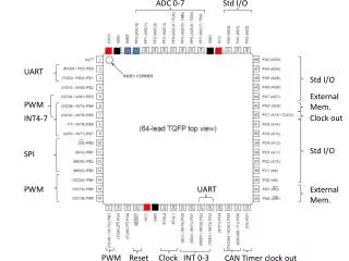
UARTs • Usually used on simple systems • Typically point to point communications • Various different formats and protocols • Normally 8-bit data format with one start and one stop bit • Standards: E.g. RS232 • defines connector type, pin assignments, voltage levels, max bit rate, cable length etc. • Min. 3 pins – TxD, RxD, Ground • Other pins for data flow control. • Some common RS232 baud rates - 300,1200,9600,19200 • Handshaking • None • Hardware - RTS, CTS, etc - simple logic levels • Software - Xon/Xoff protocol
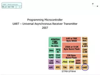
The LPC23xx UARTs • UART1 is identical to UART0/2/3, but with the addition of a modem interface. • 16 byte Receive and Transmit FIFOs. • Register locations conform to ‘550 industry standard. • Receiver FIFO trigger points at 1, 4, 8, and 14 bytes. • Built-in baud rate generator. • Standard modem interface signals included (CTS,DTS, DTR, RTS). • Either software or hardware flow control can be implemented.
USART Features (1/2) • 3USARTs: USART1 & USART6 on High speed APB2 and USART2,3,4,5 on Low speed APB1 • Fully-programmable serial interface characteristics: • Data can be 8 or 9 bits • Even, odd or no-parity bit generation and detection • 0.5, 1, 1.5 or 2 stop bit generation • Programmable baud rate generator • Integer part (12 bits) • Fractional part (4 bits) • Baud rate for standard USART (SPI mode included) Tx/Rx baud = fck/8x(2-OVR8)xUSARTDIV • Where: • Tx/Rx baud: desired baudrate • OVR8: oversampling by 8 (1 if enabled, 0 if disabled) • fck: APB frequency • USARTDIV: value to be programmed to the BRR register
USART Features (2/2) • Support hardware flow control (CTS and RTS) • Dedicated transmission and reception flags (TxE and RxNE) with interrupt capability • Support for DMA • Receive DMA request and Transmit DMA request • 10 interrupt sources to ease software implementation • LIN Master/Slave compatible • Synchronous Mode: Master mode only • IrDA SIR Encoder Decoder • Smartcard Capability • Single wire Half Duplex Communication • Multi-Processor communication • USART can enter Mute mode • Mute mode: disable receive interrupts until next header detected • Wake up from mute mode (by idle line detection or address mark detection) • Support One Sample Bit method: allows to disable noise detection (for noise-free applications) in order to increase the receiver’s tolerance to clock deviations.