Download
1 / 98
1.01k likes | 1.21k Views
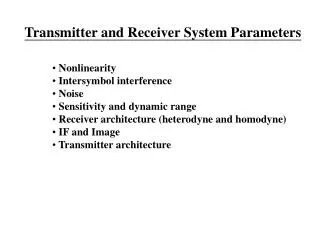
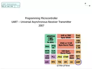
Universal Asynchronous Receiver Transmitter. Dr. V. K ëpuska. BF533 UART Port Controller. Reference: ADSP-BF533 Blackfin Processor Hardware Reference (doc: BF533-5689413713358021532_hwr.pdf). BF533 UART Port Controller. The Universal Asynchronous Receiver/Transmitter (UART) is a

E N D
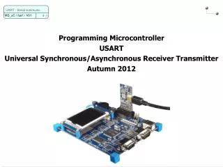
Universal Asynchronous Receiver Transmitter Dr. V. Këpuska
BF533 UART Port Controller • Reference: ADSP-BF533 Blackfin Processor Hardware Reference (doc: BF533-5689413713358021532_hwr.pdf) Veton Këpuska
BF533 UART Port Controller • The Universal Asynchronous Receiver/Transmitter (UART) is a • full-duplex peripheral compatible with PC-style industry-standard UARTs. • The UART converts data between serial and parallel formats. • The serial communication follows an asynchronous protocol that supports various • word lengths, • stop bits, and • parity generation options. • The UART includes interrupt handling hardware. Interrupts can be generated from 12 different events. Veton Këpuska
BF533 UART Port Controller • The UART is a DMA-capable peripheral with support for separate TX and RX DMA master channels. • It can be used in either • DMA or • programmed non-DMA mode of operation. The non-DMA mode requires software management of the data flow using either interrupts or polling. • The DMA method requires minimal software intervention as the DMA engine itself moves the data. See Chapter 9 of HRM, “Direct Memory Access” for more information on DMA. • Either one of the peripheral timers can be used to provide a hardware assisted autobaud detection mechanism for use with the UART. See Chapter 15 of HRM, “Timers,” for more information. Veton Këpuska
Serial Communication • The UART follows an asynchronous serial communication protocol with these options: • 5 – 8 data bits • 1, 1½, or 2 stop bits • None, even, or odd parity • Baud rate = SCLK/(16 × Divisor), where SCLK is the system clock • frequency and Divisor can be a value ranging from 1 to 65536 • All data words require a start bit and at least one stop bit. With the optional parity bit, this creates a 7- to 12-bit range for each word. • The format of received and transmitted character frames is controlled by the Line Control register (UART_LCR). Data is always transmitted and received least significant bit (LSB) first. Veton Këpuska
Bitstream on the TX Pin Veton Këpuska
UART Control and Status Registers • The processor provides a set of PC-style industry-standard control and status registers for each UART. • Control and Status Registers are Memory Mapped Registers (MMR). • These Memory-Mapped Registers (MMRs) are byte-wide registers (16-bits) that are mapped as half words with the most significant byte zero filled. • Divisor Latch Registers: (UART_DLH and UART_DLL) • Transmit Holding Register: (UART_THR) • Receive Buffer Register: (UART_RBR) • Interrupt Enable Register: (UART_IER). • Consistent with industry-standard interfaces, multiple registers are mapped to the same address location. • The Divisor Latch Access bit (DLAB) in the Line Control Register (UART_LCR) controls which set of registers is accessible at a given time. Software must use 16-bit word load/store instructions to access these registers. • Transmit and receive channels are both buffered. • The UART_THR register - buffers the Transmit Shift register (TSR) and • The UART_RBR register - buffers the Receive Shift register (RSR). The shift registers are not directly accessible by software. Veton Këpuska
UART Control and Status Registers: UART Line Control Register • UART_LCR Register • The UART Line Control Register (UART_LCR) controls the format of received and transmitted character frames. • The SB bit functions even when the UART clock is disabled. • Since the TX pin normally drives high, it can be used as a flag output pin, if the UART is not used. Veton Këpuska
UART Control and Status Registers: Modem Control Register • UART_MCR Register • The Modem Control Register (UART_MCR) controls the UART port, as shown in Figure 13-3. • Even if modem functionality is not supported, the Modem Control register is available in order to support the loopback mode. Loopback mode forces the TX pin to high and disconnects the receiver’s input from the RX pin, but redirects it to the transmit output internally. Veton Këpuska
UART Control and Status Registers: UART Line Status Register • UART_LSR Register • The UART Line Status Register (UART_LSR) contains UART status information as shown in Figure 13-4. Veton Këpuska
UART Line Status Register • The following bits are cleared when the UART Line Status Register (UART_LSR) is read: • The Break Interrupt (BI), • Overrun Error (OE), • Parity Error (PE) and • Framing Error (FE). • The Data Ready (DR) bit is cleared when the UART Receive Buffer Register (UART_RBR) is read. • Important Note: • Because of the destructive nature of these read operations, special care should be taken. For more information, see “Speculative Load Execution” on page 6-69 and “Conditional Load Behavior” on page 6-70. Veton Këpuska
UART Line Status Register • The THRE bit indicates that the UART transmit channel is ready for new data and software can write to UART_THR. • Writes to UART_THR clear the THRE bit. • It is set again when data is copied from UART_THR to the Transmit Shift register (TSR). • The TEMT bit can be evaluated to determine whether a recently initiated transmit operation has been completed. Veton Këpuska
UART Control and Status Registers: UART_THR Register • A write to the UART Transmit Holding register (UART_THR) initiates the transmit operation. • The data is moved to the internal Transmit Shift Register (TSR) where it is shifted out at a baud rate equal to SCLK/(16 × Divisor) with start, stop, and parity bits appended as required. Veton Këpuska
UART_THR Register • All data words begin with a 1-to-0-transition start bit. • The transfer of data from UART_THR to the Transmit Shift register (TSR) sets the Transmit Holding Register Empty (THRE) status flag in the UART Line Status register (UART_LSR). • The write-only UART_THR register is mapped to the same address as the read-only UART_RBR and UART_DLL registers. • To access UART_THR, the DLAB bit in UART_LCR must be cleared. • When the DLAB bit is cleared, • writes to this address target the UART_THR register, and • reads from this address return the UART_RBR register. • Note data is transmitted and received least significant bit (LSB) first (bit 0) followed by the most significant bits (MSBs). Veton Këpuska
UART Control and Status Registers: UART_RBR Register • UART_RBR Register • The receive operation uses the same data format as the transmit configuration, except that the number of stop bits is always assumed to be 1. • After detection of the start bit, the received word is shifted into the Receive Shift Register (RSR) at a baud rate of SCLK/(16 x Divisor). • After the appropriate number of bits (including stop bit) is received, the data and any status bits are updated and the Receive Shift Register is transferred to the UART Receive Buffer register (UART_RBR), shown in Figure 13-6. • After the transfer of the received word to the UART_RBR buffer and the appropriate synchronization delay, the Data Ready (DR) status flag is updated. Veton Këpuska
UART_RBR Register • Sampling Clock Issues: • A sampling clock equal to 16 times the baud rate samples the data as close to the midpoint of the bit as possible. • Because the internal sample clock may not exactly match the asynchronous receive data rate, the sampling point drifts from the center of each bit. • The sampling point is synchronized again with each start bit, so the error accumulates only over the length of a single word. • A receive filter removes spurious pulses of less than two times the sampling clock period. • The read-only UART_RBR register is mapped to the same address as the write-only UART_THR and UART_DLL registers. • To access UART_RBR, the DLAB bit in UART_LCR must be cleared. • When the DLAB bit is cleared, • writes to this address target the UART_THR register, while • reads from this address return the UART_RBR register. Veton Këpuska
UART Control and Status Registers: UART_IER Register • UART_IER Register • The UART Interrupt Enable Register (UART_IER) is used to enable requests for system handling of empty or full states of UART data registers. • Unless polling is used as a means of action, the ERBFI and/or ETBEI bits in this register are normally set. Veton Këpuska
UART_IER Register • Non DMA data transfers • Setting this register without enabling system DMA causes the UART to notify the processor of data inventory state by means of interrupts. • For proper operation in this mode, system interrupts must be enabled, and appropriate interrupt handling routines must be present. • For backward compatibility, the UART_IIR still reflects the correct interrupt status. • Important Note: The UART features three separate interrupt channels to handle data transmit, data receive, and line status events independently, regardless whether DMA is enabled or not. Veton Këpuska
UART_IER Register • DMA data transfers • With system DMA enabled, the UART uses DMA to transfer data to or from the processor. Dedicated DMA channels are available to receive and transmit operation. • Line error handling can be configured completely independently from the receive/transmit setup. • The UART_IER register is mapped to the same address as UART_DLH. To access UART_IER, the DLAB bit in UART_LCR must be cleared. Veton Këpuska
UART_IER Register: DMA • UART’s DMA is enabled by • first setting up the system DMA control registers, and then • enabling the UART ERBFI and/or ETBEI interrupts in the UART_IER register. • Depending on whether DMA is enabled or not, upon receiving these requests, the DMA control unit either • generates a direct memory access, or • passes the UART interrupt on to the system interrupt handling unit. • However, UART’s error interrupt goes directly to the system interrupt handling unit, bypassing the DMA unit completely. Veton Këpuska
UART_IER Register: DMA • The ELSI bit enables interrupt generation on an independent interruptchannel when any of the following conditions are raised by the respective bit in the UART Line Status register (UART_LSR): • Receive Overrun Error (OE) • Receive Parity Error (PE) • Receive Framing Error (FE) • Break Interrupt (BI) • When the ETBEI bit is set in the UART_IER register, the UART module immediately issues • an interrupt or • DMA request. • When initiating the transmission of a string, no special handling of the first character is required. • Set the ETBEI bit and let the interrupt service routine load the first character from memory and write it to the UART_THR register in the normal manner. • Accordingly, the ETBEI bit should be cleared if the string transmission has completed. Veton Këpuska
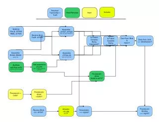
UART Control and Status Registers: UART_IIR Register • UART_IIR Register • For legacy reasons, the UART Interrupt Identification register (UART_IIR) still reflects the UART interrupt status. Legacy operation may require bundling all UART interrupt sources to a single interrupt channel and servicing them all by the same software routine. • This can be established by globally assigning all UART interrupts to the same interrupt priority, by using the System Interrupt Controller (SIC). • When cleared, the Pending Interrupt bit (NINT) signals that an interrupt is pending. • The STATUS field indicates the highest priority pending interrupt. • The receive line status has the highest priority; • the UART_THR empty interrupt has the lowest priority. • In the case where both interrupts are signaling, the UART_IIR reads 0x06. • When a UART interrupt is pending, the interrupt service routine (ISR) needs to clear the interrupt latch explicitly. The following figure (next slide) shows how to clear any of the three latches. • The TX interrupt request is cleared by • writing new data to the UART_THR register or by • reading the UART_IIR register. • Please note the special role of the UART_IIR register read in the case where the service routine does not want to transmit further data. Veton Këpuska
UART Control and Status Registers: UART_IIR Register • UART_IIR Register Veton Këpuska
UART Control and Status Registers: UART_IIR Register • If software stops transmission, it must read the UART_IIR register to reset the interrupt request. • As long as the UART_IIR register reads 0x04 or 0x06 (indicating that another interrupt of higher priority is pending), the UART_THR empty latch cannot be cleared by reading UART_IIR. • Important Note: • If either the Line Status interrupt or the Receive Data interrupt has been assigned a lower interrupt priority by the SIC, a deadlock condition can occur. To avoid this, always assign the lowest priority of the enabled UART interrupts to the UART_THR empty event. • Because of the destructive nature of these read operations, special care should be taken. For more information, see “Speculative Load Execution” on page 6-69 and “Conditional Load Behavior” on page 6-70. Veton Këpuska
UART Control and Status Registers: UART_DLL and UART_DLH Registers • UART_DLL and UART_DLH Registers • The bit rate is characterized by the system clock (SCLK) and the 16-bit Divisor. • The Divisor is split into the UART Divisor Latch Low Byte register (UART_DLL) and • The UART Divisor Latch High Byte register (UART_DLH). • Both registers together form a 16-bit Divisor. • The baud clock is divided by 16 so that: • BAUD RATE = SCLK/(16 x Divisor) • Divisor = 65,536 when UART_DLL = UART_DLH = 0 Veton Këpuska
UART_DLL and UART_DLH Registers • The UART_DLL register is mapped to the same address as the UART_THR and UART_RBR registers. • The UART_DLH register is mapped to the same address as the Interrupt Enable register (UART_IER). • The DLAB bit in UART_LCR must be set before the UART Divisor Latch registers can be accessed. • Important Note: • The 16-bit Divisor formed by UART_DLH and UART_DLL resets to 0x0001, resulting in the highest possible clock frequency by default. • If the UART is not used, disabling the UART clock will save power. The UART_DLH and UART_DLL registers can be programmed by software before or after setting the UCEN bit. Veton Këpuska
UART_DLL and UART_DLH Registers Veton Këpuska
UART Control and Status Registers: UART_SCR Register • UART_SCR Register • It is used for general-purpose data storage and does not control the UART hardware in any way. • The contents of the 8-bit UART Scratch register (UART_SCR) is reset to 0x00. Veton Këpuska
UART Control and Status Registers: UART_GCTL Register • UART_GCTL Register • The UART Global Control register (UART_GCTL) contains the enable bit for internal UART clocks and for the IrDA (Infra-red Data Association) mode of operation of the UART. Veton Këpuska
UART_GCTL Register • The IrDA TX Polarity Change bit and the IrDA RX Polarity Change bit are effective only in IrDA mode. • The two force error bits, FPE and FFE, are intended for test purposes. They are useful for debugging software, especially in loopback mode. Veton Këpuska
DMA Mode of UART • In this mode, separate receive (RX) and transmit (TX) DMA channels move data between the UART and memory. • The software does not have to move data, it just has to set up the appropriate transfers either through • the descriptor mechanism or • through Autobuffer mode. • No additional buffering is provided in the UART DMA channel, so the latency requirements are the same as in non-DMA mode. However, the latency is determined by the bus activity and arbitration mechanism and not by the processor loading and interrupt priorities. • For more information, see Chapter 9, “Direct Memory Access.” Veton Këpuska
DMA Mode of UART • DMA interrupt routines must explicitly write 1s to the corresponding DMA IRQ status registers to clear the latched request of the pending interrupt. • The UART’s DMA is enabled by first setting up the system DMA control registers and then enabling the UART ERBFI and/or ETBEI interrupts in the UART_IER register. • This is because the interrupt request lines double as DMA request lines. • Depending on whether DMA is enabled or not, upon receiving these requests, the DMA control unit either • generates a direct memory access or • passes the UART interrupt on to the system interrupt handling unit. • However, the UART’s error interrupt goes directly to the system interrupt handling unit, bypassing the DMA unit completely. • The UART’s DMA supports 8-bit operation. Veton Këpuska
BF533 Direct Memory Access - DMA BF533 DMA Support
Processor Memory Architecture • SPORTs, • SPI port, • UART, and • PPI. Veton Këpuska
BF533 DMA Support • The processor has multiple, independent DMA controllers that support automated data transfers with minimal overhead for the core. • DMA transfers can occur between • the internal memories and any of its DMA-capable peripherals. • Additionally, DMA transfers can be accomplished between any of the DMA-capable peripherals and external devices connected to the external memory interfaces, including the SDRAM controller and the asynchronous memory controller. DMA-capable peripherals include the • SPORTs, • SPI port, • UART, and • PPI. • Each individual DMA-capable peripheral has at least one dedicated DMA channel. Veton Këpuska
BF533 DMA Support • The DMA controller supports both • one-dimensional (1D) and • two-dimensional (2D) DMA transfers. • DMA transfer initialization can be implemented from registers or from sets of parameters called descriptor blocks. • The 2D DMA capability supports arbitrary row and column sizes up to 64K x 64K elements, and arbitrary row and column step sizes up to +/- 32K elements. Furthermore, the column step size can be less than the row step size, allowing implementation of interleaved data streams. This feature is especially useful in video applications where data can be de-interleaved on the fly. Veton Këpuska
Generic Names of the DMA Memory-Mapped Registers Veton Këpuska
Analysis of Basic UART Implementation Communication of BF533 EZ-Kit Lite via RS-232 UART
UART RS-232 Veton Këpuska
UART Configuration in DMA Mode /******************************************************** Function to configure the UART & DMA ********************************************************/ void setup_UART() { // Clear the DMA configuration register *pDMA7_CONFIG = 0x0; // Configure the UART DMA parameter registers // Transmit DMA *pDMA7_START_ADDR = tx_buffer; *pDMA7_X_COUNT = BUFFER_SIZE; *pDMA7_X_MODIFY = 1; // Autobuffer DMA Continously transmit the data *pDMA7_CONFIG = 0x1081; Veton Këpuska
UART Control Registers Configuration // Configure the UART Control Registers // Enable the divisor latch access *pUART_LCR = 0x0080; *pUART_DLH = 0x0000; *pUART_DLL = 0x01FF; // disable the divisor latch access *pUART_LCR = 0x0000; //Enable 8-bit mode without parity with 2 Stop Bits *pUART_LCR = 0x0007; //Enable interrupts for transmit *pUART_IER = 0x0002; // UART Clock Enabled *pUART_GCTL = UCEN; } Veton Këpuska
DMA Channel’s Peripheral Map Register • Each DMA channel’s Peripheral Map register (DMAx_PERIPHERAL_MAP) contains bits that: • Map the channel to a specific peripheral. • Identify whether the channel is a Peripheral DMA channel or a Memory DMA channel. *pDMA7_PERIPHERAL_MAP = 0x7000; Veton Këpuska
UART Configuration in DMA Mode /******************************************************** Function to configure the UART & DMA ********************************************************/ void setup_UART() { // Clear the DMA configuration register *pDMA7_CONFIG = 0x0; // Configure the UART DMA parameter registers // Transmit DMA *pDMA7_START_ADDR = tx_buffer; *pDMA7_X_COUNT = BUFFER_SIZE; *pDMA7_X_MODIFY = 1; // Autobuffer DMA Continously transmit the data *pDMA7_CONFIG = 0x1081; Veton Këpuska
DMA Configuration Register • The DMA Configuration register (DMAx_CONFIG/MDMA_yy_CONFIG), shown in Figure 9-3 of ADSP-BF533 Blackfin Processor Hardware Reference, also in this slide is used to set up DMA parameters and operating modes. Veton Këpuska
UART Configuration in DMA Mode /******************************************************** Function to configure the UART & DMA ********************************************************/ void setup_UART() { // Clear the DMA configuration register *pDMA7_CONFIG = 0x0; // Configure the UART DMA parameter registers // Transmit DMA *pDMA7_START_ADDR = tx_buffer; *pDMA7_X_COUNT = BUFFER_SIZE; *pDMA7_X_MODIFY = 1; // Autobuffer DMA Continously transmit the data *pDMA7_CONFIG = 0x1081; Veton Këpuska
Transmit_uart_533.c /******************************************************* This example code tests the UART using the stop mode DMA across two kits. This code is the transmitter code. *******************************************************/ #include <CdefBF533.h> #include <defBF533.h> #include <signal.h> #include <sys/exception.h> #define BUFFER_SIZE 16 /******************************************************* Function declarations *******************************************************/ void setup_UART(); void setup_interrupts(); /******************************************************* ISR declarations *******************************************************/ EX_INTERRUPT_HANDLER(transmit_isr); /******************************************************* Variable declarations *******************************************************/ char tx_buffer[BUFFER_SIZE]; volatile unsigned int tx_cnt = 0; Veton Këpuska
DMA Start Address Register • The Start Address register (DMAx_START_ADDR/MDMA_yy_START_ADDR), shown in Figure 9-2 of ADSP-BF533 Blackfin Processor Hardware Reference, also in the next slide, contains the start address of the data buffer currently targeted for DMA. Veton Këpuska
UART Configuration in DMA Mode /******************************************************** Function to configure the UART & DMA ********************************************************/ void setup_UART() { // Clear the DMA configuration register *pDMA7_CONFIG = 0x0; // Configure the UART DMA parameter registers // Transmit DMA *pDMA7_START_ADDR = tx_buffer; *pDMA7_X_COUNT = BUFFER_SIZE; *pDMA7_X_MODIFY = 1; // Autobuffer DMA Continously transmit the data *pDMA7_CONFIG = 0x1081; Veton Këpuska