Download
1 / 73
730 likes | 732 Views
This text discusses the parameters and design considerations for a beam emittance diagnostic in the FCC-ee, including the expected spectrum, brightness, and photon energy. It also explores the use of a pinhole camera for beam profile/size monitoring in the high-energy range.

E N D
Conceptual design for SR monitor In the FCC Beam emittance (size) diagnostic T. Mitsuhashi KEK
Beam profile in phase space b=20m a=2 a=1 a=0 Y’ (rad) Y (m)
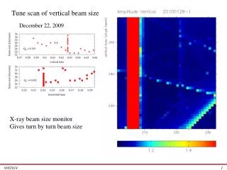
175GeV r=11590.8m 0.1nm Divergence of beam Order of 10-7rad Divergence of SR Order of 10-5rad q in rad
Expected spectrum from the bending magnet FCC-ee 45GeV 175GeV Brightness (photons / mrad2 1%bandwidth) Frequency integrated power 174W/ 20mrad for 175GeV 172W/20mrad for 45GeV Photon energy (keV)
Character of bending magnet in FCC-ee 24.858m or 2.144mrad Bending angle of 2.144 mrad is 100 times larger than tail to tail opening of SR at 0.1nm (0.002mrad). So, this bend is classified as long magnet. TR from magnet edge is week enough in X-ray region. Bending radius 11590.8m
Angular diameter q a d Object locates having a size a at certain distance d Angular diameter is given by, q=a/d
Extraction of hard X-rays from the ring • Light source • use last bending magnet in Arc.
Estimated vacuum duct 45-50mm
100m 24.858m 2.144mrad 50m 107.2mm 1.072mrad 53.6mm Geometrical condition for the extraction of SRfrom the last bending magnet Enough separation between orbit and extraction structure of the vacuum duct is necessary to escape from corrective effect. Some similar structure such as crotch absorber and branch optical beam line seems necessary to protect the crotch of the vacuum chamber from strong irradiation of SR. Bending radius 11590.8m
Comment for X-ray pinhole camera Start with physics of pinhole.
A simple X-ray pinhole camera should be convenient for beam profile/size monitor in high energy range
y’ y’ y’=(-y+h)/s pinhole h/s y y h h On the source point Representation of the pinhole in the phase space and matching between the source point On the pinhole
Pinhole in phase space on source point h=y+sy’ y’=(-y+h)/s
y’ In the case of short wavelength such as X-ray y’=(-y+h)/s In the case of longer wavelength, ellipsoid will smeared by large opening angle of radiation h/s h y Phase space plot of proton beam
Diffraction phenomena in pinhole camera
Intensity of diffraction is given by Fresnel transform of pupil function F of the pinhole Thus, in the case of simple circular hole
t=f/(a2/l)<1 t=f/(a2/l)>3 Fresnel like region Franhofer like region For example, l=0.1nm, a=2mm Franhofer region > 0.12m
In most case, pinhole with x-rays should be Franhofer region. l=0.1nm a=2mm (D=4mm) F=10m 100mm
3mm 1mm 2mm 4mm 5mm Diffraction patterns for several pinhole size
Diffraction width as a function of pinhole diameter l=0.1nm, F=10m Geometrical resolution becomes higher Diffraction resolution higher
An example of pinhole camera measurement setup Diffraction size should be 100mm Pinhole D=4mm Observation plane at 10m Beam 1s=10mm 1m 10m Geometrical magnification=10 Geometrical image size should be 100mm Without convolution between pinhole diameter Result of beam size should be 14mm without convolution of pinhole diameter
Large transverse magnification will necessary for obtaining an enough image size vs. diffraction width.
Where we can insert the pinhole?? 100m 24.858m 2.144mrad 50m 107.2mm 1.072mrad 53.6mm Some special structure, near by the beam, we mast great take care for corrective effect to the beam in Electron machine. Small impedance (smooth structure ) is strictly necessary!
Assuming we can set a pinhole at 35mm from the beam ( almost same condition in SR extraction mirror in the B-factory), corresponding distance from the source point is 35m, and putting a image sensor at 100m downstream, geometrical magnification is 1.857, so image size for 5mm beam is 9.3mm. Diffraction width of pinhole with 10mm diameter at 67m downstream is 600mm. So, 9.3mm image size is hopeless to measure.
Total reflection by surface of pinhole blocks Good surface should be necessary to make small gap of two blocks 10mm gap with 3mm length 3.33mrad
Totally reflection by surface of pinhole blocks Good surface should be necessary to make small gap of two blocks 10mm gap with 3mm length 3mrad It’s smaller than total reflection critical angle for heavy metal
Before move to X-ray interferometry, let us review relationship between image and spatial coherence in inverse space for understanding of what is the interferometry. Because image in real space is only usable for geometrical optics.
In real space Incoherent illumination Aberration free lens system Ii I0 Optical transfer function, OTF input output H gi g0 In space
g0=F (I0 ) F ( ) : Fourier transform gi=F (Ii ) H =F ( ) : Optical transfer function Then gi=H g0 Ii = F (H g0 )
r Example of OTR Lens has pupil of radius r and focal length di Cut off frequency of OTR twice of CTF cut off frequency di
Singlet D=80mm f=1000mm l=0.55mm
Doublet D=80mm f=1000mm l=0.55mm
In the interferometry g0 given byg0=F (I0 ) is equal to the spatial coherence g through Van Cittelt-Zernike’s theorem as follows; Then g0= g . So, we can measure image in inverse space without OTF by interferomtry.
Imaging with lens Optical transfer function, OTF Interferometry input input output output H gi gi = g0 g0 g0
Interferometry is considered as more direct method to measure image in inverse space! Since this reason, most of huge astronomical telescopes are interferometers ( Kek, VLA, ALMA)
K-edge filter Double slitD=20-few100mm, a=8mm Be-window 100m 50-100m Simple double slit X-ray interferometer (Young type)
175GeV r=11590.8m Double slit location We do not need selection of polarization Iv / Ih =0.016 q in rad
Double slit of interferometer will not miss the beam size information Divergence of SR Order of 10-5rad Divergence of beam Order of 10-7rad
Double slit interferometer (Young type) with total reflection mirror K-edge filter Double slitD=20-100mm, a=8mm g-ray 1.0-1.5deg Be-window Totally reflection mirror Length of 0.3m 100m 100m
Spatial coherence vs. beam size D=300um, f=100m l=0.10nm g Beam size (mm)
Expected interferogram for g=0.65 (beam size of 5mm at 100m) Double slit a=5um, D=300um f=100m Monochromatic l=0.1nm
Absorption of Krypton gas K-edge filter (1 atm, 100 mm pass). Krypton gas filter has a nice window around 10keV
With quasi-monochromatic ray Kr gas filter 100mm Dl/l=20% Dl/l=50%
Shift in two optical axis Dl/l=20%
Background subtraction problem Log scale plot for the interference fringe with two diffraction envelopes of slit