Download
1 / 21
210 likes | 346 Views
Angela Saa Hernandez, Martin Rohrer, Volker Schlott , Andreas Streun (PSI, Switzerland ) Jonas Breunlin, Åke Andersson (MAX IV Laboratory, Sweden) Natalia Milas (LNLS, Brazil ). The new Beam Size Monitor at SLS. existing ( ) and planned ( ). Intro.

E N D
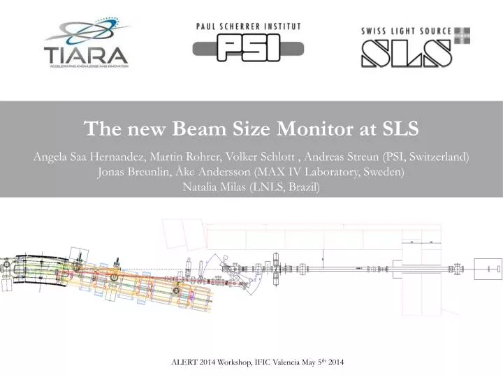
Angela Saa Hernandez, Martin Rohrer, Volker Schlott , Andreas Streun (PSI, Switzerland) Jonas Breunlin, Åke Andersson(MAX IV Laboratory, Sweden) Natalia Milas (LNLS, Brazil) The new Beam Size Monitor at SLS ALERT 2014 Workshop, IFIC Valencia May 5th 2014
existing ( ) and planned () Intro • Some years ago a program was launched at SLS towards the minimization of the vertical equilibrium emittance… • beam assisted realignment of girders • correction of roll errors in BPMs • Model-based and random correction schemes • using skew quadrupoles Minimization of β-coupling and vertical dispersion Horizontal and Vertical Emittances of Storage Rings • vertical beam size: 3.6 ± 0.6 μm • vertical emittance: 0.9 ± 0.4 pm M. Aibaet al., Ultra Low Vertical Emittance at SLS Through Systematic and Random Optimization, NIM-A 694 (2012) 133-139 How was that measured? Can we improve it? Figure taken from: R. Bartolini, Low EmittanceRing Design, ICFA Beam Dynamics Newsletter, No. 57, Chapter 3.1, 2012 – and updated. ALERT 2014 Workshop, IFIC Valencia May 5th 2014
Measurement of small beam sizes at SLS non-invasive diagnostics→imageformationmethodsusingsynchrotron radiation from bending magnets Horizontal (σ) polarization Horizontal (σ) polarization 7/8 total power Vertical (π) polarization Vertical (π) polarization 1/8 total power electron beam SR spectrum from bending magnet (1.4 T @ 2.4 GeV) ALERT 2014 Workshop, IFIC Valencia May 5th 2014
Measurement of small beam sizes at SLS non-invasive diagnostics→imageformationmethodsusingsynchrotron radiation from bending magnets A standard tool: x-ray pinhole at SLS CCD camera Pinholes: Ø 15, 20, 25 and 30 μm in 150 μm W plate P43 fluorescent screen CVD diamond 100 μm CVD diamond 100 μm lens BX09 mirror Electron beam movable Mo attenuator Pinholes <0.2 mrad 4 – 25 keV (depending on Mo filters) PSF : 9 -25 μm → prone to errors for σy < PSF Image = Source profile * PSF ALERT 2014 Workshop, IFIC Valencia May 5th 2014
Measurement of small beam sizes at SLS non-invasive diagnostics→imageformationmethodsusingsynchrotron radiation from bending magnets A high resolution tool: π-polarized visible/UV monitor at SLS Å. Andersson et al., Determination of Small Vertical Electron Beam Profile and Emittance at the Swiss Light Source, NIM-A 592 (2008) π-polarized visible/UV monitor 0.45 mrad < vertical angle < 4.5 mrad Wavelength > 180 nm (266, 325, 365, 405, 532…) Pinholes <0.2 mrad 4 – 25 keV (depending on Mo filters) ALERT 2014 Workshop, IFIC Valencia May 5th 2014
Principle of π–polarized Imaging Monitor A high resolution tool: π-polarized visible/UV monitor at SLS • imaging of vertically polarized SR in the visible/UV • phase shift of π between two radiation lobes • → destructive interference in the mid plane • zero intensity for a point-like beam • residual intensity for a beam with finite vertical beam size • theoretical calculations with SRW for beam size determination O. Chubar& P. Elleaume, Accurate and Efficient Computation of Synchrotron Radiation in the Near Field Region,EPAC98 ALERT 2014 Workshop, IFIC Valencia May 5th 2014
Principle of π–polarized Interference Monitor A high resolution tool: π-polarized visible/UV monitor at SLS • imaging of vertically polarized SR in the visible/UV • phase shift of π between two radiation lobes • → destructive interference in the mid plane • zero intensity for a point-like beam • residual intensity for a beam with finite vertical beam size • theoretical calculations with SRW for beam size determination O. Chubar& P. Elleaume, Accurate and Efficient Computation of Synchrotron Radiation in the Near Field Region,EPAC98 ALERT 2014 Workshop, IFIC Valencia May 5th 2014
Design of the new SLS Beam Size Monitor • Higher optical magnification ratio, 1.45 (new) vs 0.84 (old) and smaller pixel size • → more active pixels on the CCD camera • → increase of measurement precision • imaging & interferometric method • → complementary measurement methods • → cross-checking of results • Longer beamline (X08DA ) • → optics table outside tunnel: accessible during machine operation • Laser front end • → alignment check of focusing element (minimize optical aberrations) • → online monitoring optical component quality with lasers at 405 and 532 nm ALERT 2014 Workshop, IFIC Valencia May 5th 2014
Installation of the new SLS Beam Size Monitor Beamline frontend dipole X08DA optical table Measurement Station in-coupling mirror mirror 2 mirror 1 interference obstacle CCD camera neutral density filters polarizer bandpass + laser line filters YAG screen ALERT 2014 Workshop, IFIC Valencia May 5th 2014
Resolution limits Simulated valley-to-peak ratios for different wavelengths and measurement methods as a function of the vertical beam size. →improved resolution (2% valley-to-peak ratio) →beam size measurements ~ 2 μm new beam size monitor old beam size monitor Pure imaging (π-polarization method) 20 mm obstacle 25 mm obstacle 15 mm obstacle • Comparison of the vertical beam size measured simultaneously with the old and the new monitor. • On the new monitor the measurement method has been changed successively. • →Consistentresults for the different methods on the new monitor (also for the different wavelengths) ALERT 2014 Workshop, IFIC Valencia May 5th 2014
From beam size to emittance Wecannotmeasuretheemittancedirectly… but wecanmeasurethe beam size. in a synchrotronβ-functionsanddispersionsarewellknown verticalemittance At the center of dipole BX08: ALERT 2014 Workshop, IFIC Valencia May 5th 2014
Results • Screenshots of the graphical interface showing the CCD camera readout for the different measurement methods. • SRW simulation result for direct comparison. • → Good agreement between measurements and simulations Measurement Measurement Measurement Measurement SRW simulation Pure imaging Interferometric method Interferometric method Interferometric method Interferometric method 15 mm obstacle 20 mm obstacle 25 mm obstacle 25 mm obstacle Smallest beam size measured so far at the new monitor in lens-based configuration, using the π-polarization imaging method σy = 4.3 ± 0.3 μm→εy = 1.3 ± 0.2 pm·rad ALERT 2014 Workshop, IFIC Valencia May 5th 2014
Monitor Upgrade (January 2014) Lens-optics Exchange of the lens for a toroidal mirror as the focusing element → free selection of SR wavelength without shift of image plane → allows broader spectral bandwidth (increases intensity on camera) → might allow shorter wavelength measurements with increase resolution Toroidal mirror-optics • But imaging with a toroidal mirror is tricky… • Critical issues: • Misalignments (offsets, tilts, rotation around axis) • Surface quality: modeled to set specifications Commissioning • →Testbench where to image in parallel with a twin toroidalmirror • → Limiting aperture on light path: ongoing work to realign beamline • → Adjustment of incident angles (tight constrained with toroid-optics) by tilting gimbal mount ALERT 2014 Workshop, IFIC Valencia May 5th 2014
Summary New high resolution beam size monitor installed at SLS → application of complementary measuring methods (π-polarization/interferometric) → expected measurements resolution for vertical beam height ~ 2 μm → commissioned for lens-optics, measured εy= 1.3 ± 0.2 pmrad so far → upgrade (toroidal focusing mirror) provides an easier selection of SR wavelength but commissioning is tricky and still ongoing Thankyoufor your attention!!! ALERT 2014 Workshop, IFIC Valencia May 5th 2014
Additional slides ALERT 2014 Workshop, IFIC Valencia May 5th 2014
Critical issues: misalignments Toroidal mirror used for imaging → peak/valley ratio extremely sensitive to misalignments SRW simulations used to define constraints on mechanical alignment Offsets • horizontal offset Dx • vertical offset Dy → not critical within ± 50 μm Tilts and Axis Rotation horizontal tilt Tx symmetric broadening and and washing out of peak-to-valley pattern rotation around mirror axis R and vertical tilt Ty asymmetric washing out of peak-to-valley pattern for R & Ty ALERT 2014 Workshop, IFIC Valencia May 5th 2014
Critical issues: surface quality Surface errors modify path length →modeled to set specifications of optical elements M. Sanchez del Rio and A. Marcelli, Waviness effects in ray-tracing of real optical surfaces, NIM-A 319 (1992) Model principle + met by the manufacturers… L ALERT 2014 Workshop, IFIC Valencia May 5th 2014
Pre-Requisites and Tools for Vertical Emittance Tuning 1.high beam stability as a pre-requisite top-up operation → high thermal (long term) stability precise BPMs: ~ 100 nm rms (< 100 Hz) fast orbit feedback orbit control & short term stability 2.procedures & equipment for vertical emittance tuning re-alignment (beam-assisted girder alignment) of storage ring → remote positioning of 48 girders skew quadrupoles for coupling control (36 in case of SLS) → sextupoles with additional coils high resolution beam size monitor ALERT 2014 Workshop, IFIC Valencia May 5th 2014
Procedure for SLS Vertical Emittance Tuning 1. measurement and correction of BPM roll error → avoid “fake” vertical dispersion readings (from 48 dispersive BPMs with ηx≠ 0) 2. realignment of magnet girder to remove main sources of vertical dispersion → reduction of rms vertical correction kick from ~ 130 μrad to ~ 50 μrad 3. measurement & correction of vertical dispersion and betatron coupling → model-based skew quadrupole corrections (12 dispersive and 24 non-dispersive skew quads) 4. “random walk” optimization of vertical beam size → skew quadrupole corrections using beam size measurements from profile monitor σ y = 3.6 ± 0.6 μm ε y = 0.9 ± 0.4 pm M. Aiba, et al., Ultra Low Vertical Emittance at SLS Through Systematic and Random Optimization, NIM-A 694 (2012) 133-139 CLIC Workshop 2013 ALERT 2014 Workshop, IFIC Valencia May 5th 2014
Maintenance and non(yet)-solved problems • Fused silica elements get UV damaged → deteriorate imaging quality and eventually need to be replaced flat mirror lens exit window • Image vibrations at the camera 50 – 100 μm rms • → (unknown spectrum but exposure time <0.5 ms to avoid image blurring) • Beamlinerelated (laser suffers them)! ALERT 2014 Workshop, IFIC Valencia May 5th 2014