Download
1 / 13
130 likes | 136 Views
VEX Units of work. UNIT 1: TUMBLER. UNIT 2: CLAWBOT. UNIT 3: MANUFACTURING. UNIT 1.1: Autodesk Inventor TUMBLER Build. UNIT 2.1: Autodesk Inventor CLAWBOT Build. UNIT 3.3 Autodesk Inventor UNIQUE Parts. Project Overview. CNC Introduction Applying CNC Designing for CNC

E N D
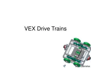
VEX Units of work UNIT 1: TUMBLER UNIT 2: CLAWBOT UNIT 3: MANUFACTURING UNIT 1.1: Autodesk Inventor TUMBLER Build UNIT 2.1: Autodesk Inventor CLAWBOT Build UNIT 3.3 AutodeskInventor UNIQUE Parts
Project Overview • CNC Introduction • Applying CNC • Designing for CNC • CNC Manufacture • Open Design for CNC Challenge • Total VEX Robotics manufacture
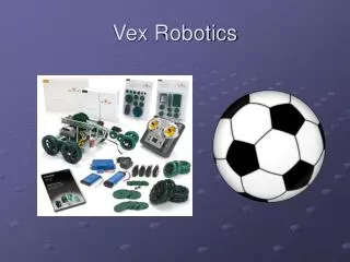
Computer Numerical Control Computer Numerical Control is the collective term for all application of computer operated machinery to the manufacture of components and products. VEX Robotics parts are made using a wide variety of CNC machines and processes. Project Brief“In this micro project, you are going to learn about modern industrial fabrication processes, the role CNC plays in industry, and how to design and make using CAD and industrial CAM. The project will challenge you to design simple new VEX EDR parts, before embarking on the full fabrication of a VEX EDR Clawbot. The project will use Autodesk software to develop parts, and fabrication of these will take place using a plasma or laser cutter, with post processing taking place in the school workshop using common metal working techniques. Structural parts will be based on the fundamental approaches of working with sheet material to make nets or folding parts, but use the high tolerance and aesthetic design of VEX EDR. At the end of the project you will need to be able to evidence how you designed, made, checked and tested your parts, and will need to submit a working commercially viable finished robot solution.” For more information about products and competition opportunities go to www.vexrobotics.com Key words: 3D printing, batch, mass production, injection moulding.
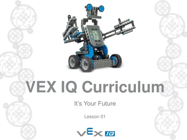
Lesson 01 Starter Learning objective: Learn about different types of CNC, the role and application of CNC in industry, and be able to identify how CNC could be used to enhance robotic solutions. CNC is now common place in education, but in industry it has been a method of production since the 1940’s, when numerically controlled machines used a punch tape for motors to follow. Modern servomotor controls operate using either analogue or digital computer signals.Examples of CNCMilling – machines moving a cutter through X, Y and Z axis, and classified as either a 3, 4, 5 or 6 axes machinesLathe – machines where material is spun in a centred chuck, and tooling moves in an X or Z axisPlasma Cutting – similar to laser cutting, a plasma torch melts the sheet metal awayEDM – electrical discharge machining uses spark/hole/wire erosion to remove material via electric sparksWater jet – a high pressured water and abrasive mix is fired at high velocity through material to cut it Key termsG-Code – a standardised programme language that machines can interpret. Key words: CAD, Library, heat processes, acrylic, MDF, profile, forming.
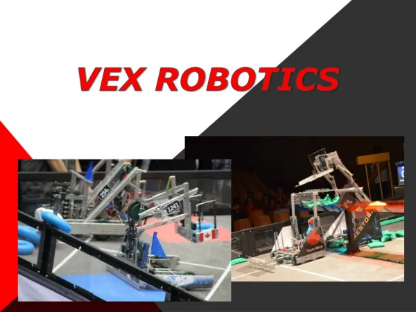
Computer Numerical Control Technique: Computer Numerical Control VEX sheet steel components are manufactured using computer numerical control. No other method would manufacture such high quality, high accuracy parts. Stock material, sheet steel, is cut by transferring the data from a digital file to a CNC machine, where a cutter is moved through 2 axis (X & Y) via servomotors to cut the path of the digital line work. Given the nature and potential of different types of CNC processes, the steel could be cut by plasma, water jet, EDM or even milling to create the perfectly finished parts.
Computer Numerical Control What does plasma cutting look like? Industrial scale plasma cutting machines are, large, powerful pieces of equipment that perform exactly like education specific machines. Often bed size and power differentiate the machines by price, whilst the ability to cut thicker material is more applicable to industry than schools because of the weight of the material.With all cutting and fabrication using computer controlled equipment, the role of the CAD design and CAM operator are key to the production of successful parts. The skills and knowledge of each of these people will decide how accurate and commercially viable the produced parts are for post processing and assembly into modern robotic solutions. In conjunction with
Computer Numerical Control Plasma cut VEX parts Watch the video of plasma cutting VEX parts to create a standard Clawbot. Questions to considerWhat are features of the process?What contributes to the accuracy and speed of the process?Why does the process spark?What is the purpose of the water?Why does the metal part curve up at the end of the cut?What would the operator set up at the start of each job? In conjunction with
Computer Numerical Control Plasma cut VEX parts For the job of cutting VEX EDR parts, the plasma cutter was set up with the following parameters. What do each of them mean/contribute to the outcome of the cut?In your pairs, discuss each heading and try to decide:- what is being changed here- what the affect would be if it were higher or lower
Computer Numerical Control Laser cut VEX parts Watch the video of an industrial laser cutter cutting VEX parts to create a standard Clawbot. Questions to considerWhat are features of the process?What contributes to the accuracy and speed of the process?Why does the process spark?How does this process differ to the last?Why do you think this process is more accurate?What would the operator set up at the start of each job? In conjunction with
Lesson 01 Plenary As a class, let us consider the following questions?A. What skills and knowledge does a CAM operator need?B. What could go wrong when cutting using CAM?C. How are accurate parts achieved using CAD/CAM?D. What potential does plasma and laser cutting of steel have on the production of robotic parts in the future?
Lesson 01 Summary Learning objective: Learn about different types of CNC, the role and application of CNC in industry, and be able to identify how CNC could be used to enhance robotic solutions. • Today you have: • Learnt about Computer Numerical Control. • Be able to identify how CNC is used in industry. • Propose how CNC might enhance robotics and robotic solutions.