Download
1 / 17
170 likes | 180 Views
VEX UNITS OF WORK. UNIT 1: TUMBLER. UNIT 2: CLAWBOT. UNIT 3: MANUFACTURING. UNIT 1.1: Autodesk Inventor TUMBLER Build. UNIT 2.1: Autodesk Inventor CLAWBOT Build. UNIT 3.2 Laser Cutting. Project Overview. Structural part Introduction Laser cutting & forming Model Making

E N D
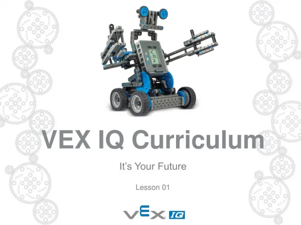
VEX UNITS OF WORK UNIT 1: TUMBLER UNIT 2: CLAWBOT UNIT 3: MANUFACTURING UNIT 1.1: Autodesk Inventor TUMBLER Build UNIT 2.1: Autodesk Inventor CLAWBOT Build UNIT 3.2 Laser Cutting
Project Overview • Structural part Introduction • Laser cutting & forming • Model Making • Designing & Developing • Manufacturing • Building & Analysing
Manufacturing Introduction Whether you are new to the world of VEX Robotics, or a seasoned robotics engineer, the opportunity to design and manufacture your own unique VEX parts offers huge opportunity to be creative.Whilst robotic solutions you develop will not be allowed to compete in the national competition, the process of design and manufacture will develop a highly sought after range of skills. In this project, the world of engineering and manufacture are completely at your finger tips. You are challenged to reimagine the VEX Robotics platform, through a series of short design and make projects. The first stage will focus on more complex geometric parts made by 3D printing PLA and ABS filament. The second stage will focus on structural components made by laser cutting acrylics and sheet woods. The final stage will look at the application of CNC machines to create parts in more resistant materials including sheet and block steels and aluminium. For more information about products and competition opportunities go to www.vexrobotics.com
Laser cutting Introduction As a process, laser cutting is relatively common in both industry and education, due to the affordable nature of high powered machines with the ability to cut through a range of resistant materials. With the advent of 2D software packages that create DXF files, students are now able to manufacture products to the same standard as industry using the power and accuracy of high powered lasers under computer control.Laser cutting is a process designed for batch production of parts in man made woods, sheet plastics which do not have a chlorine base, and card or paper. As the process can be more powerful by using a higher watt laser, there is also opportunity to cut aluminium's and steels. A laser can be used to cut on high power settings, or engrave and etch at lower powers. The speed can also be varied to create passing cuts or to reduce the burning affect of the laser on the material surface. In the world of VEX Robotics, sheet steels and aluminium's have been processed by laser to create 2D profiles which can either be packaged for sale, or formed into unique shapes. Using typical Computer Numerical Control (CNC). Parts can be cut by melting, burning, vaporising or blowing away the material under the direct line of the laser. For more information about products and competition opportunities go to www.vexrobotics.com Key words: 3D printing, batch, mass production, injection moulding.
Lesson 01 Starter Learning objective: Learn about the design of structural parts including the use of templates, uniform and standardised dimensions, tolerances, and the application of laser cutting technology. As part of this project, you have access to a CAD library of template files for existing VEX Robotics parts. Whilst these parts are manufactured in galvanised steel or aluminium, and then formed into angled or C channel profiles, you will initially start by working with MDF or laser ply sheets which will not subsequently be formed, you will then progress quickly onto acrylic sheets which can subsequently be formed using heat processes. Definition: CAD LibraryIs a shared digital library of part and component files of standard and off the shelf parts used repeatedly in the assembly of larger products. Key words: CAD, Library, heat processes, acrylic, MDF, profile, forming.
Structural Parts Important features of structural parts Sheet material can be dramatically strengthened by bending it. If the bend is accurate and sharp, the material can then be aligned to other parts as a larger assembly.VEX Robotics metal parts are either galvanised steel or aluminium. Their hole allocation are the same for each part, and bends in the material are always 90 degrees.
Structural Parts Tolerance of VEX components relate to every measurement of the part, from hole size, to position, to length, width and thickness. Understanding tolerances Tolerance relates to the level of accuracy that a component is made to. It is expressed as a percentage (%). Here is an example:If a component is designed at 100mm long and has a tolerance of +/- 5%, it means the length can measure up to 5% longer or 5% shorter than 100mm and still be acceptable to the manufacturer.Therefore its longest length can be 105mm, and its shortest length can be 95mm, and still be classed to be in tolerance. Do you think products with a higher tolerance (i.e. a smaller % number) are more or less expensive to make?Why?
Structural Parts Laser cutting acrylic to make VEX As part of this project, you are going to laser cut parts from a CAD library, and design your own CAD files to laser cut unique robot parts. Some of these will remain in 2D form, but others might be bent and formed into 3D shapes (similar to nets) to create unique engineered solutions for your robot. Simple form acrylic parts for panels, shunts, pushers and scoops. Bent and formed acrylic parts to form 3D connection points. Integrating metal VEX screws and existing components into an assembly of made and bought parts. The original VEX parts you will replace (some aluminium, some steel, some painted, some 3D and some 2D)
Structural Parts Process: Laser Cutting Task: Make a page of notes and sketches about your laser cutter and the process of laser cutting.Laser cutting is a very precise method of cutting a design into sheet material using a CAD file to guide it. A common type of laser used in education, a CO2 laser, fires a focused beam through a focal lens at material in close proximity, which will melt, burn or vaporise the material. Lasers create a kerf, a slight angle on the material cut out which results in the base being wider than the top, as the laser enters the material from above and therefore is removing material slightly more here as it passes over the sheet.CAD files are prepared on an industry standard software packaging such as AutoCAD, before moving to a specialised specific software package that runs the laser cutter. Settings for the power and speed of the laser are entered and assigned to different coloured lines, meaning different types of cutting, engraving and etching can take place in the same job. Final parts need little or no finishing to the edge, but residual waste material might remain on the surface of an etched or engraved feature in the form of fine white powered.
Structural Parts Machine study: Laser Cutter This laser cutter, by CTR Lasers, is a CO2 machine. The size of the machine means the laser can travel over an area of up to A1 paper, a total of 564mm x 841mm.The laser is most powerful at its sources (origin) which is identified on the photo by a red circle. Therefore in the opposite corner (bottom right) the laser has travelled the farthest, and will therefore not be as powerful (and not cut the material).The laser is powerful enough to cut through sheet plastic and wood at close range (10mm from the laser head), but will not cut metals (which will reflect the laser back up).The power of a laser is measured in watts. This one is 65W.
Structural Parts Machine study: Laser Cutter Aluminium bars are very common in industry as the bed. This is because they are easy to remove and clean, and are machined to a high level of accuracy. The alternative to bars is a honeycomb mesh of steel. These panels with screws behind them are mirrors. The laser is actually fired from a box at the bottom of the machine upwards, and mirrors bounce the beam off themselves to the nozzle. The nozzle is where the laser leaves the machine and travels through the material below it. The laser is only powerful close to the nozzle. Just a few centimetres below this (the bar height) the laser is no longer powerful enough to cut anything. These marks are evidence of MDF (Medium Density Fibreboard) being cut by a laser. The glue in the material vaporises, leaving sticky residue on the aluminium bars directly underneath the laser.
Structural Parts Machine study: Laser Cutter The machine has a stop button. Though the laser cannot move outside of a safe area of cutting, the settings can be too high for the material, causing it to catch fire in some instances. The laser cutter must filter the fumes coming off the machine whilst it is running. This is because, in vaporising the material using the laser, the material has turned into fine particles that if breathed in, would cause considerable damage to your lungs. A red dot allows the path of the laser to be seen, before the laser cuts (lasers cannot be seen by the naked eye) A datum is a 0,0 position on a flat surface. It is from here that the laser will start its programme. It is important to test your programme before cutting, to see if your material is the right size.
Structural Parts Designing laser cut parts The features of your laser cut parts will be; accurate; 2D or folded into 3D; rigid by design; flexible by design; unique.Task: Design some simple 2D and 3D net style VEX parts for the Clawbot robot Bend lines (with heat) zz Rule 1:Try to avoid designing simply larger versions of existing parts. Multiple parts joined together solves that issue over larger parts. Rule 2:Avoid making parts that create material waste. The centre of this part is wastage. Four strips would be a better solution here. Rule 3:Think of your parts beyond their 2D form. Laser cutting is an excellent process when you do something with the outcomes rather than accept them as they come out. Do more with them.
Lesson 01 Plenary As a class, let us consider the following questions?A. How does tolerance play a part in the manufacture of everyday products?B. In what instances is tolerance and dimensional accuracy more vital and higher?C. How does laser cutting technology provide higher level accuracy?D. Where else are standardised design features applied in products?
Summary Learning objective: Learn about the design of structural parts including the use of templates, uniform and standardised dimensions, tolerances, and the application of laser cutting technology. • Today you have: • Learnt about how structural engineering parts are designed to interlock and work together. • Learnt about the important of tolerance and dimensional accuracy in component manufacture. • Learnt about the appropriate application of laser cutting technology in design and engineering.