Download
1 / 13
130 likes | 247 Views
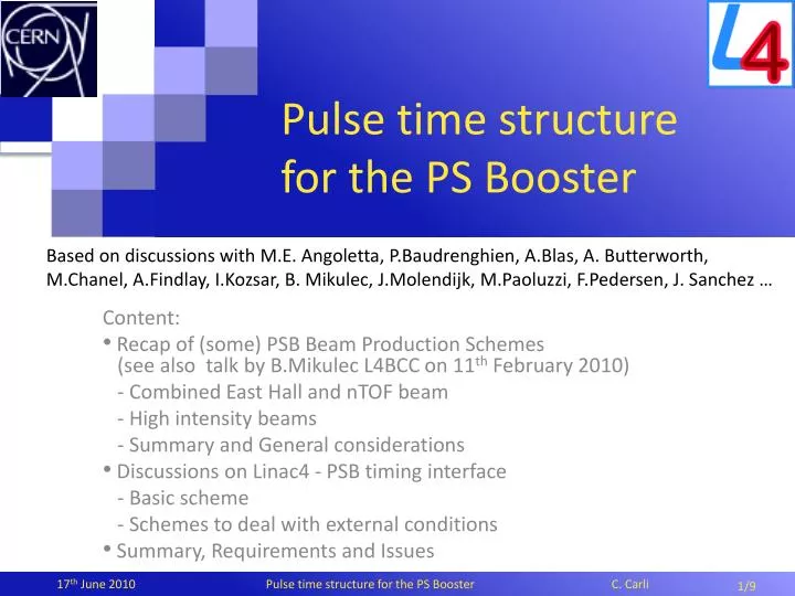
Pulse time structure for the PS Booster. Based on discussions with M.E. Angoletta , P.Baudrenghien , A.Blas , A. Butterworth, M.Chanel , A.Findlay , I.Kozsar , B. Mikulec , J.Molendijk , M.Paoluzzi , F.Pedersen , J. Sanchez …. Content:

E N D
Pulse time structure for the PS Booster Based on discussions with M.E. Angoletta, P.Baudrenghien, A.Blas, A. Butterworth, M.Chanel, A.Findlay, I.Kozsar, B. Mikulec, J.Molendijk, M.Paoluzzi, F.Pedersen, J. Sanchez … Content: Recap of (some) PSB Beam Production Schemes (see also talk by B.Mikulec L4BCC on 11th February 2010) - Combined East Hall and nTOF beam - High intensity beams - Summary and General considerations Discussions on Linac4 - PSB timing interface - Basic scheme - Schemes to deal with external conditions Summary, Requirements and Issues 1/9
Recap of (some) PSB Beam Production Schemes Combined East Hall and nTOF beam Chopper • Chopper pulse (upper part) and beam structure (lower part) to generate two bunches • Low intensity in ring 3 for East Hall • High Intensity in ring 2 for nTOF • Injection on flat bottom without longitudinal painting for nTOF (not maximum brightness) • Linac4 beam pulse length and (and distributor timings) depend on beam to be produced • Booster timing system triggers distributor and source stop (like “tailclipper” for Booster) • Watch out for residual beam (chopping inefficiency) during beginning and end of pulse! • Execution as programmed without external condition suppressing beam (see later) Ibeam Injection ring 3: low intensity with few short beam slices 1 - 10 turns > 20 ms LEBT stabilization Injection ring 2: “high” intensity ~0.5 ms beam slices in waiting buckets during 20 to 50 turns Beam switch off (how?) Pre-chopper off Distributor(s) to ring 3 immediately … and no beam head (L4BCC #2) !! Distributor switching to tail dump Distributor switching ring 3 to ring 2 2/9
Recap of (some) PSB Beam Production Schemes High brightness & intensity beams (LHC, ISOLDE, CNGS?) • Aim: Optimize bunching factor for highest beam brightness/intensity • Principle: • Saw-tooth energy modulation of Linac4 beam • Linac4 chopper letting only bunches, ending inside waiting PSB bucket, through • Baseline (2007) under discussion: • Energy modulation period > 20ms, amplitude ±1.2 MeV and momentanous spread sE=0.12MeV • Already too high intensity for LHC with nominal 65mA peak current • Under discussion: minimum energy modulation period - how to use that in the Booster Injection on ramp into waiting buckets 3/9
Recap of (some) PSB Beam Production Schemes High brightness & intensity beams (LHC, ISOLDE, CNGS?) > 20 ms LEBT Stabilization & beam head ? Injection ring 4 One to five energy modulations Injection ring 3 Injection ring 2 Injection ring 1 > 20 ms source switch off • For illustration energy modulation within 20 turns • Injection on ramp -> differences of field of the four rings at time of filling compensated by “Bdl”s Longitudinal painting: • Chopper pulse and energy modulation (dashed line) • Beam structure (lower part) Small energy offset Long Linac4 trains Large energy offset short Linac4 trains one energy modulation period > 20 turns (in this example) 4/9
Recap of (some) PSB Beam Production Schemes Summary and General • Booster requires flexible programming of injected L4 beam pieces (and energy modulation) • Assumption that the four Booster rings will be synchronized (to common reference) • Chopper timings sequence (and Linac4 energy modulation predetermined) from an initial trigger synchronized with common Booster reference • Compatible as well with zero RF voltage (and capture) at injection • Beam to head and tail dumps (before filling ring 4 and after filling ring1)? • No “beam head” required for L4 low level RF with feedforward beam loading compensation • How well can the beam be suppressed (pre-chopper, chopper, ….) • Linac4 beam pulse length and (and distributor timings) depend on beam produced • Full Linac4 beam pulse for low intensity may be quite short (NOT always 100 ms/ring) • Booster timing system triggers distributor and source stop (like “tailclipper” for Booster) • External conditions: may require suppressing filling of one or more rings • E.g. request removed by experiment (for example above: nTOF may removes request, but East Hall bunch still to be generated) • Failure of equipment (e.g. ejection kicker) still allowing beam in other Booster rings • Intervention by operations team during setting up or MDs (e.g. to have beam only in one ring) … • External conditions may change frequently … say up several times during one hour • Must suppress filling of one (or more) ring(s) without reprogramming injection sequence 5/9
Discussions on Linac4 PSB timing interfaceBasic scheme Trigger from Booster to L4 VRF,PSB • Aim: simplicity by decoupling PSB and L4 as much as possible • Several schemes have been discussed in 2009 • Finally agreed basic scheme: • One single trigger sent from PSB to L4 to start L4 beam generation and Booster injection • Chopper on/off timings defined in L4 RF periods from this trigger • Complexity delegated to high level application • Extension to deal with external condition required Ibeam Linac4 RF train time 6/9
Discussions on Linac4 PSB timing interfaceExternal Conditions – Veto signal from Booster One single trigger from PSB to L4 starting beam Distributor switching beam ring 4 to ring 3 Distributor switching ring 3 to ring 2 Proposal by Philippe et al • Additional Beam-off (veto) signal provided by the PSB timing system to Linac4 • Unwanted beam to be removed by chopper (on durations up to to 300 ms or 400 ms) • No change of Booster injection hardware timings depending on external conditions • Generation of “veto-signal” to be integrated into Booster injection timing system • mall Linac4 beam current in case of imperfect chopping • Veto to Booster RF as well (as now with Linac2) … not a serious issue for activation • Strong beam loading transients VRF, Ibeam Veto Chopper timings from one single trigger counting on L4 RF train Injection ring 2 No beam injection into ring 3 Injection ring 4 7/9
Discussions on Linac4 PSB timing interfaceExternal Conditions – advance filling of rings Ring 3 (injection programmed) left out, trigger to L4 for ring 2 Trigger to L4 for injection in ring 4 Trigger to L4 for injection in ring 1 • Skip ring not to be filled and advance filling of rings later in the injection sequence • Requires chopper on/off timing (and energy modulation) definitions and triggers from PSB individually for each ring …. Synchro of Booster rings not really required! • Reduced Linac4 pulse length and maximum chopper on durations • Changes slightly magnetic field at injection into rings filled earlier • Ruled out due to L4 low level RF constraints: • More complex hardware to deal with individual triggers per ring • Problematic for Linac4 adaptive feedforward compensation VRF, Ibeam Chopper timings using individual ring-by-ring triggering (and counting on L4 RF train) Injection ring 4 Injection into ring 2 Injection ring 1 8/9
Summary, Requirements and Issues • Summary • Various schemes proposed to generate the large variety of Booster beams • Details may change … sufficient flexibility to adapt to different (future) needs • Linac4 beam pulse adjusted to Booster intensity (short pulses for low intensity) • Discussions on synchronization of the L4 beam pulse to Booster needs well advanced • Including external conditions … may change several times during one hour • Requirements and (related) Issues … Booster view • Control over Linac4 beam structure (chopper timings) and energy modulation (as fast as possible – under discussion at present) synchronized with RF of ring filled • Different energy spreads and beam currents (feasibility?, minimum/maximum? …)! • Total L4 pulse length adjustment (H- source, pre-chopper, L4 RF …?) • Good chopping efficiency before, during and and after useful beam pulse • Losses on head (internal – decision at L4BCC #2) and tail dump to be estimated • Short chopper off (beam on) time (20-30 ns o.k.) and fast rise/fall times • Interlocks (within the present or next pulse?): hardware to “shape” the beam for regular operation (chopper and pre-chopper?) not necessarily suitable for interlock cutting L4 beam • Agreement on basic interfacing between Linac4 and Booster • Specification of new Booster low level RF and application to program beam pulse generation, design of Booster timing system … . • Operation with pre-chopper only: is this still an option to be investigated? 9/9
Ideas to lengthen the energy modulation period (requiring other means to limit intensity) • Reduction of the Linac4 peak beam current • In PPM mode for the “USER” concerned • Special optics creating losses on chopper dump proposal by A. Lombardi & team • Injection “only” every second (or third …) turn • Requires Linac4 low level RF system to deal with “long” (a few ms) beam gaps • Longitudinal painting: • Chopper pulse and energy modulation (dashed line) • Beam structure (lower part) time Injection into one ring with one energy modulation period (lasting 26 turns in this example) Chopper pulse and beam currents versus time
Other PSB Injection Schemes with Linac4 • Injection of coasting beams • No PSB RF voltage at injection, RF capture (possibly after filamentation) • for example for very low intensities or creating structure with pre-chopper • Example below for low intensity beams (with not too small transverse emittances) • Energy spread: fill 80% of bucket AL=1.73 eVs after capture • Trev2 51/2sE< 0.8 AL => sE< 0.3 MeV (or larger for shaving for low intensities ?) Injection ring 4 1 to 10 pieces of ~40 ns per revolution Injection ring 3 1 to 10 pieces of ~40 ns per revolution Injection ring 2 & 1 structure like rings 4 & 3 > 20 ms LEBT stabilization > 20 ms source switch off Beam head (if necessary) Distributor switching beam head to ring 4 Distributor switching ring 4 to ring 3 Distributor switching ring 3 to ring 2 Distributor switching ring 1 to tail dump
Other PSB Injection Schemes with Linac4 • Injection into waiting buckets without energy modulation • “intermediate” intensities • painting not practical, but reduced losses • Energy spread: sE≅ 1 MeV/51/2 = 450 keV Trev Injection ring 4 ~0.5 ms/revolution Injection ring 3 ~0.5 ms/revolution Injection ring 2 & 1 structure like rings 4 & 3 > 20 ms LEBT stabilization > 20 ms source switch off Beam head (if necessary) Distributor switching beam head to ring 4 Distributor switching ring 4 to ring 3 Distributor switching ring 3 to ring 2 Distributor switching ring 1 to tail dump
Introduction to the Subject - Situation without action …. and ideas to be discussed from 1st Meeting on 19th March Slide from 2nd L4BCC on 16th June 2009 Proposal (others exist): Bring beam head out of SMV on external head dump (dump above line acceptable ?) Head dump in SMV tank ? • Questions & Ideas for possible upgrades: • - How much activation at 160 MeV instead of 50 MeV • - Is Beam Head (how much) needed for Linac4 RF • Can 3 MeV chopper upgrade help? • Can upgrade of pre-chopper help Tail dump in tank