Download
1 / 14
140 likes | 307 Views
PS Booster 2 GeV upgrade - Magnets. Subjects Transfer line magnets Auxiliary ring magnets (multi-pole, correctors etc...) Main ring Quadrupole magnets (32 QF & 16 QD) Main ring Dipole magnets (30 Normal, 2 Special & 1 Reference) New main ring magnets. PS Booster 2 GeV upgrade.

E N D
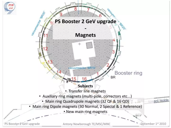
PS Booster 2 GeV upgrade - Magnets • Subjects • Transfer line magnets • Auxiliary ring magnets (multi-pole, correctors etc...) • Main ring Quadrupole magnets (32 QF & 16 QD) • Main ring Dipole magnets (30 Normal, 2 Special & 1 Reference) • New main ring magnets PS Booster 2 GeV upgrade December 1st 2010 Antony Newborough TE/MSC/MNC
Transfer line and Auxiliary ring magnets • Transfer line magnets • BT: 24 Magnets • BTM: 6 Magnets • BTP: 15 Magnets • Cost estimate: 1.4 MCHF (18/45 magnets) • Several magnets need to be measured & have alternative powering scenarios explored. BT.BHZ.10 - TBH • Auxiliary ring magnets • Multi-poles (QNO,ONO, OSK etc...): 112Magnets • Correctors (DHZ, DVT): 72 Magnets • Used at low energy 6 * BTP Quadrupoles • Critical magnet for LHC operation • No spare unit available • Not adequate for 2 GeV operation • Consolidation project is on hold until PS injection layout is defined. • Constructed 1971 • Limit for 2 GeV operation • Solid Yoke (non PPM) • Suitable design available PS Booster 2 GeV upgrade December 1st 2010 Antony Newborough TE/MSC/MNC
Main Ring Quadrupole Magnets • Findings: • Increase of field strength seems feasible • Field quality is not affected • This preliminary study will be cross checked with measurements • Power increase will require modifications to the cooling circuit • Magnets are far from saturation PS Booster 2 GeV upgrade December 1st 2010 Antony Newborough TE/MSC/MNC
Main Ring Quadrupole Magnets – Power and cooling • Removal of the Eletta flow switches will give an increase of flow, allowing for up to a 10 % increase in RMS current without an increase of pressure or temperature. To compensate for the removal of the flow switches additional thermal switches would be installed. Tests are ongoing. • The connections types are to be reviewed to increase the reliability of the magnets. PS Booster 2 GeV upgrade December 1st 2010 Antony Newborough TE/MSC/MNC
Main Ring Dipole Magnets • Initial Findings: • Increase of field strength seems feasible • Field quality does not seem to be affected with 2D analysis. • Magnetic measurements confirm the initial study and are ongoing. • Power increase will require modifications to the cooling circuit. • Due to higher saturation of the outer rings a higher current differential than present is required, which may be compensated for. • Higher forces require modifications to the coil shimming method. PS Booster 2 GeV upgrade December 1st 2010 Antony Newborough TE/MSC/MNC
Main Ring Dipole Magnets - Power and cooling • Removal of the Eletta flow switches will give an increase of flow, allowing for up to a 10 % increase in RMS current. To compensate for the removal of the flow switches additional thermal switches would be installed. Tests are ongoing. • The connections types are to be reviewed to increase the reliability of the magnets. PS Booster 2 GeV upgrade December 1st 2010 Antony Newborough TE/MSC/MNC
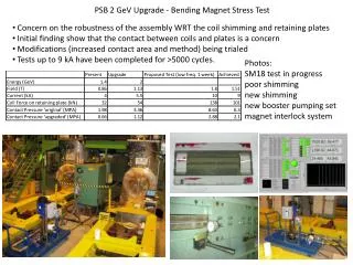
Main Ring Dipole Magnets - Saturation and shimming • Concerns over the robustness of the assembly WRT the coil shimming and retaining plates. • Initial findings showed that the contact between coils and plates is a concern. • Modifications to increase the contact area and method of shimming have been trialed with • a peak current of 9 kA. • Installation work could take place in the machine at the same time as the new laminated • plates (assuming agreement from radio protection) • Tests are to be carried out to determine the reliability of the yoke side shimming. However, • if modifications are required all magnets would need to be removed from the machine. PS Booster 2 GeV upgrade December 1st 2010 Antony Newborough TE/MSC/MNC
Main Ring Dipole Magnets - Saturation and shimming The majority of the difference in field between the inner and outer rings (approx. 1% @ 1.4 GeV, 4% @ 2 GeV) may be compensated with laminated plates and implemented in parallel to the shimming modifications. • Reducing the saturation: • Improves the repeatability of the magnetic cycle. • Decreases the RMS current in the outer rings decreasing any additional temperature rise. • Advantages for power supply configuration. PS Booster 2 GeV upgrade December 1st 2010 Antony Newborough TE/MSC/MNC
Main Ring Dipole Magnets - Saturation and shimming Special injection and extraction magnets • Special Coil configuration to allow the beam to enter and exit the machine. • laminated plates more difficult to implement, but not impossible. • Initial modeling seems to be promising. PS Booster 2 GeV upgrade December 1st 2010 Antony Newborough TE/MSC/MNC
Main Ring Dipole Magnets – Reference Magnet • Proto-type Bending Magnet • Ground fault during 2009 High Voltage test • All coils in series • Existing coils would need to be separated or replaced to run with two M.P.S. and two B-train measurements. • No current means of removing the magnet from Booster convertor room. PS Booster 2 GeV upgrade December 1st 2010 Antony Newborough TE/MSC/MNC
Main Ring Magnets – New Magnets • Why consider new magnets? • Reliability issues with the old magnets? • Cost / Power savings • What can be done? • Increase of conductor section and # turns • Increase of iron section to remove saturation effects of outer rings • Consideration must be given to: • Cost of new magnets • Weight of new magnets (~ 18 tonnes) • Space constraints • Radio active waste (old magnets, ~ 80 m^3) • Installation time • Vacuum and accessories • Power convertors OLD NEW PS Booster 2 GeV upgrade December 1st 2010 Antony Newborough TE/MSC/MNC
Main Ring Magnets – New Magnets • Magnet Circuit Resistance – Unchanged • ~ 500 mΩ (Main Dipole magnets ~ 344 mΩ, Main Quadrupole magnets ~ 130 mΩ) • Magnet Circuit Inductance – To more than double • ~ 146 mH (Main Dipole magnets ~ 132 mH, Main Quadrupole magnets ~ 14 mH) PS Booster 2 GeV upgrade December 1st 2010 Antony Newborough TE/MSC/MNC
TE-MSC-MNC - Conclusions • Transfer Line Magnets • A number of magnets must be changed for 2 GeV operations • Different powering configurations can be explored to save some magnets, D.C. Cycling to pulsed mode. • All BTP Quadrupole magnets should be changed to laminated versions. • Auxiliary ring magnets are not concerned by the 2 GeV upgrade. • The Main ring magnets • Can be operated at 2 GeV with: • Modification to the coil shimming and the new laminated plates are desirable, if not 100% necessary. • Minor in-situ modifications when the increase in RMS current is <= 10% (RP approval still required). • Major modifications to the cooling circuit when the RMS current is increase by more than 10% (Magnets would need to be removed from the machine). • New magnets may be considered to explore reliability, power and cost savings. PS Booster 2 GeV upgrade December 1st 2010 Antony Newborough TE/MSC/MNC
Thank you for listening - Discussion PS Booster 2 GeV upgrade December 1st 2010 Antony Newborough TE/MSC/MNC