Download
1 / 19
190 likes | 347 Views
Review on PS Booster with L4. Upgrade of Distribution and Injection Region Wim Weterings TE/ABT Thanks to many colleagues for their contribution, in particular: B. Balhan, J. Borburgh, T. Fowler, B.Goddard, M. Hourican, A. Prost, L. Sermeus 15-01-2009. Talk Overview.

E N D
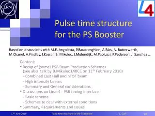
Review on PS Booster with L4 Upgrade of Distribution and Injection Region Wim Weterings TE/ABT Thanks to many colleagues for their contribution, in particular: B. Balhan, J. Borburgh, T. Fowler, B.Goddard, M. Hourican, A. Prost, L. Sermeus 15-01-2009
Talk Overview • Beam Separation Principle • Required Modifications • Beam Distribution (BI.DIS) • LINAC4 Pulse Structure • Beam Separation (BI.SMV) • H- charge-exchange Injection System • Principle • Status • Layout and Available Space • Main Design Parameters • Present Status • Conclusion W. Weterings - LINAC4 PSB Review
Booster Injection Principle LINAC4 W. Weterings - LINAC4 PSB Review
Booster Injection Principle Vertical Septum BI.SMV & BI.BVT Beam slices are further deflected by the BI.SMV septa into the BI.BVT vertical dipole apertures to achieve the required booster beam level separation of 360 mm between each ring Proton Distributor BI.DIS system of pulsed magnets, which kick slices of the beam to different vertical positions at the vertical septum BI.SMV H- Charge-Exchange Injection System 160 MeV H- beam from LINAC4 is injected through a graphite stripping foil to convert ~98% of the beam to protons, using two independent closed orbit bump systems W. Weterings - LINAC4 PSB Review
Required Modifications for LINAC 4 Relocate modified KSW1L1 magnet to PSB period 16, build new pulse generator. Remove obsolete BI.DIS Pb ~0.36 Tm required from BI.BVT for ~175mrad@160MeV Modify BI.DIS for4.3 mrad @ 160 MeV New BI.SMV,4 mm thick septum and 70 mm horizontal aperture for ~165 mrad @ 160 MeV with associated new pulse generator. • Rebuild the 2.654 m injection region of each of the 4 PSB rings: • 4 new BS magnets, • Foil holder and handler, • Dump for unstripped H0/H-, • Beam Instrumentation. Performance increase of 1.9 in ∫B•dl of BI.DVT30, BI.QNO30, BI.QNO40, BI.DVT40. W. Weterings - LINAC4 PSB Review
3.65 Booster Injection Principle Beam Distribution Proton Distributor BI.DIS • LINAC4 beam enters the BI.DIS with a ~5.2 mm vertical offset. • The BI.DIS system, in combination with BI.DVT40, kicks slices of the beam into the septa BI.SMV. • a ~3.5 mrad deflection producing a vertical beam separation of 35 mm at the BI.SMV. • In case of BI.DIS failure, the full beam is deflected by BI.DVT40 into an absorber block (head-dump). W. Weterings - LINAC4 PSB Review
DIS 0 DIS 0 DIS 1 DIS 1 DIS 2 DIS 2 DIS 3 DIS 3 HeadDump (60µs) DIS 4 DIS 4 20 to 100µs 1µs 1µs Ring 4 Ring 3 Ring 2 Ring 1 3 ~ 5µs Booster Injection Principle LINAC4 Pulse Structure Proton Distributor BI.DIS • 4 individual LINAC4 pulses, typically 20~100µs long with 1µs gap for BI.DIS rise-time. • Fixed BI.DIS pulse lengths, but different for each magnet. • Timing to be adjusted according to required number of injection turns from pulse to pulse. Example: Operation 20~100 injected turns/ ring Example: Pilot Beams 3~5 injected turns/ ring Tail Dump (20µs) W. Weterings - LINAC4 PSB Review
Booster Injection Principle Status Proton Distributor BI.DIS • Magnet design optimised, • Vacuum vessel designed and ordered for April 2009 • Ferrite blocks delivered for all magnets, • prototype coil & magnet built, • Mechanical supports delivered, • Custom current transformers delivered, • HV and magnetic tests imminent, • HV feedthrough under study, • Limited space available for magnet protection elements, • Planned to have 2 operational BI.DIS by end 2009 W. Weterings - LINAC4 PSB Review
Booster Injection Principle Beam Separation Magnetic Septa BI.SMV • The rising edge of the LINAC4 pulse is deflected to a absorber block (head dump). • BI.SMV septa deflect the beam vertically into apertures of 3 separate BI.BVT vertical dipole magnets to achieve the required PSB beam level separation of 360 mm between each ring. • Beam designated for ring 3 will see no magnetic field and passes between SMV2 and SMV3. • The falling edge of the LINAC4 pulse is deflected to a second absorber block (tail dump). 138.75 mrad SMV 3 Head Dump SMV 2 Tail Dump -130.3 mrad SMV 1 -170.3 mrad W. Weterings - LINAC4 PSB Review
Booster Injection Principle Status Magnetic Septa BI.SMV • Magnet cross-section designed, • Vacuum vessel and magnet layout under study, • Curved laminated yoke technologyto be validated spring 2009, • Yoke forming tool ordered, • Head and Tail dump loading specified (EDMS963395) • Magnet parameters &design to be completed summer 2009. • Constraint: In case of a chopper failure, beam will be swept across BI.SMV septa blades. W. Weterings - LINAC4 PSB Review
H- Injection System Principle Booster Injection Region • Two independent closed orbit bump systems: • Injection Chicane, 4 pulsed dipole magnets (BS), located in the injection region, giving 45 mm beam offset during the injection process. • Painting Bump, 4 horizontal kickers (KSW), outside the injection region, giving 35 mm closed orbit bump with falling amplitude for transverse phase space painting. • Injected beam with -10mm horizontal offset. • BS1 must act as septum. • BS4 should accommodate internal Dump. • Stripping efficiency of ~98% expected. W. Weterings - LINAC4 PSB Review
Booster Injection Principle Status Booster Injection Region • Outside vacuum magnet design under investigation (vs inside vacuum baseline design), • Chicane fall time increased (ms range) • Undulated inconel chambers to be used, • Modified alternative magnet design to reduce lattice perturbations being studied, • BS1 will use direct drive septum geometry, • Injection concept to be finalised summer 2009, • Stripping foil carousel under study, • H0 / H- dump integrated in BS4 magnet, expected load specified in EDMS963395 (see table). Foil in position Foil retracted Top View W. Weterings - LINAC4 PSB Review
Layout and Available Space Side View Top View W. Weterings - LINAC4 PSB Review
BS4 BS2 BS3 BS1 Foil Mechanism H0 H- DUMP Layout and Available Space W. Weterings - LINAC4 PSB Review
Layout and Available Space BS4 BS3 BS1 BS2 H0 H- DUMP Foil Mechanism W. Weterings - LINAC4 PSB Review
Main Design Parameters W. Weterings - LINAC4 PSB Review
Conclusions • In order to distribute and inject the 160 MeV beam from LINAC4 into the four rings of the PSB, new distributor magnets and magnetic septa with a performance increase of 1.9 in ∫B·dl need to be built. • The pulse structure from LINAC4 will consist of 4 individual pulses, typically 65-100 μs long. The distributor pulse length will be fixed, but different for each magnet. • A completely new H- charge-exchange injection needs to be built comprising four injection dipole magnets, a stripping foil unit, an internal beam dump, and suitable instrumentation. W. Weterings - LINAC4 PSB Review
Present Status • BI.DIS - Design of new vacuum vessel completed. - Prototype magnet built. - Ferrite blocks, mechanical supports & custom current transformers delivered. - 2 operational BI.DIS by end 2009. - Currently ‘scrapers’ installed, in new design only limited space available (collimation in line...). • BI.SMV - Magnet cross-section design completed. - Vacuum vessel and magnet layout under study. - Magnet yoke forming tool ordered. - Head &Tail dump loading specified (EDMS963395), impact to be studied. - Yoke curving technology to be validated. - Horizontal aperture <70mm to be studied. W. Weterings - LINAC4 PSB Review
Present Status • BS - Basic prototype has been tested to validate OPERA™ simulations. - Outside vacuum magnet design, using undulated inconel chambers, is being studied. - Alternative magnet design to reduce lattice perturbations. • Foil Unit - Nuclear foil physics effects are being studied. - Stripping foil carousel under study. - Prototype planned for autumn 2009. • Ho/H- Dump - Expected loading specified (EDMS963395) - Thermo-mechanical studies being prepared.- H0 / H- dump integrated in BS4 magnet. W. Weterings - LINAC4 PSB Review