Download
1 / 30
310 likes | 321 Views
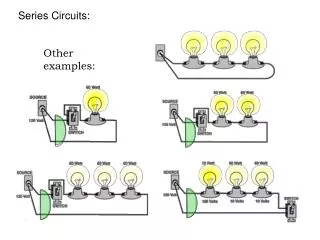
Series Circuits. Schematic Circuit Diagrams. There are many different ways to represent circuits. Below is an artist’s drawing and a schematic drawing. We will be using schematic drawings with symbols. Types of Circuits: Series.

E N D
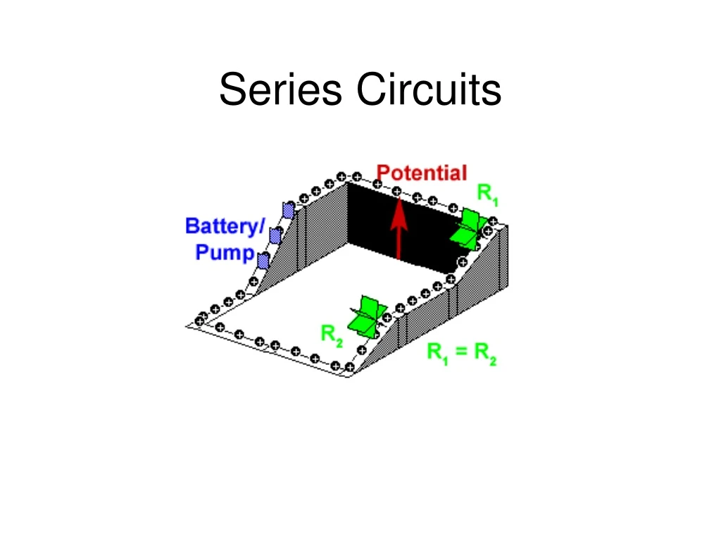
Schematic Circuit Diagrams There are many different ways to represent circuits. Below is an artist’s drawing and a schematic drawing. We will be using schematic drawings with symbols.
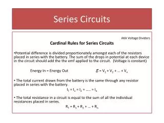
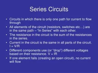
Types of Circuits: Series A series circuit can be constructed by connecting light bulbs in such a manner that there is ONE PATH for charge flow (CURRENT); the bulbs are added to the SAME LINE with no branching point- charge passes through every light bulb. Since there is only one current path in a series circuit, the current is the same through each resistor. I = I1 = I2 = I3
Types of Circuits: Series I = I1 = I2 = I3 If the current is the same everywhere within a series circuit then what is changing? V = I R http://phet.colorado.edu/sims/ohms-law/ohms-law_en.html
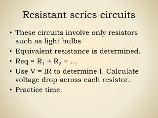
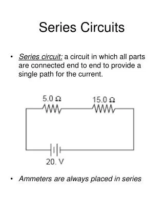
Types of Circuits: Series Let’s look at resistance: There are 3 resistors in this circuit. The total resistance of the entire circuit is called the equivalent resistance (Req). If we could replace all 3 resistors with just 1 resistor it would have the equivalent resistance of the entire circuit. Req = R1 + R2 + R3
Types of Circuits: Series Let’s look at voltage: The cell or battery of a circuit provides the total voltage allowed for the circuit. 12 V It you have a 12 V battery hooked up to your circuit then there is 12 V of “electrical pressure” pushing the current through the circuit. Current moves from an area of high pressure (12 V at the positive terminal of the battery) to an area of low pressure (0 V at the negative terminal of the battery). This is why you may often hear the term “voltage drop” across resistors. The voltage is decreasing as the current passes through resistors in the circuit because everything is together on one path. V = V1 + V2 + V3
Series Summary: IT = I1 = I2 = I3 RT = R1 + R2 + R3 VT = V1 + V2 + V3
4 Ω CW Practice #1: 36 V 6 Ω 8 Ω
CW Practice #1 Solutions: 4 Ω 36 V 6 Ω I = I1 = I2 = I3 Req = R1 + R2 + R3 8 Ω V = V1 + V2 + V3 • Req = R1 + R2 + R3 b. I = I1 = I2 = I3 Req = 4 Ω + 6 Ω + 8 Ω I = V Req Req = 18 Ω I = 36 V 18 Ω I = 2 A
V1 = I R1 c. I = 2 A V = I R V1 = (2A)(4 Ω) V1 = 8 V 4 Ω V = V1 + V2 + V3 V2 = I R2 V =8V +12V+ 16V 36 V 6 Ω V2 = (2A)(6 Ω) V = 36 V V2 = 12 V 8 Ω V3 = I R3 V3 = (2A)(8 Ω) V3 = 16 V
d. Power=? P3 = V3I = 16V(2A) = 32W P2 = V2I = 12V(2A) = 24W P1 = V1I = 8V(2A) =16W PT = P1 + P2 + P3 = 16W + 24W + 32W = 72W
CW Practice #2: 4 Ω 24 V 6 Ω 2 A A
CW Practice #2 Solutions: 4 Ω 24 V 6 Ω I = I1 = I2 = I3 Req = R1 + R2 + R3 2 A A V = V1 + V2 + V3 a. Req = V I b. Req = R1 + R2 + R3 Req = 24 V 2 A R3 = Req – R1 – R2 R3 = 12 Ω – 4 Ω– 6 Ω Req = 12 Ω R3 = 2 Ω
c. V = I R V1 = I R1 V1 = (2A)(4 Ω) V1 = 8 V 4 Ω V2 = I R2 V2 = (2A)(6 Ω) 24 V 6 Ω V2 = 12 V 2 A 2 Ω V3 = I R3 V3 = (2A)(2 Ω) V3 = 4 V
d. Power=? P3 = V3I = 4V(2A) = 8W P2 = V2I = 12V(2A) = 24W P1 = V1I = 8V(2A) =16W PT = P1 + P2 + P3 = 16W + 24W + 8W = 48W
2Ω HW Practice #1: 4 A 3Ω V
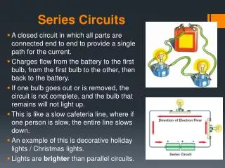
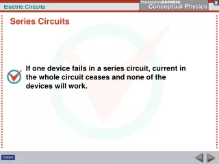
Light bulbs in Series Remember how a light bulb works? LB 2 LB 1 What will happen to LB 2 if LB 1 blows out? The circuit is no longer closed- LB 2 will also go out.
Christmas lights are connected in series. If one goes out they should all go out. But small Christmas light bulbs are designed so this doesn’t happen. Each bulb has a "shunt" of several turns of tiny wire inside the bulb near the bead. The shunt is intended to conduct current when the filament fails.
Try this… You are given 10 Ω, 20 Ω, and 30 Ω resistors, and a 3V battery. • Draw a schematic diagram of these components in a series circuit. • Determine the equivalent resistance of the circuit. • Determine the current through each resistor. • Determine the potential difference across each resistor. • Determine the power dissipated by the 20 Ω resistor.
Try this… Consider the following series circuit: • What is the potential difference between: a and b, b and c, c and d, d and a. • What is the current in the circuit? • What power is dissipated by each resistor?