Download

1 / 13
180 likes | 425 Views
Series Circuits. Principles of Physics. Simple Circuit. A circuit with one resistor When one electron leaves the voltage supply another one enters How fast this exchange occurs is based on resistance One electron pushes another and so on. Series Circuit .

E N D
Series Circuits Principles of Physics
Simple Circuit • A circuit with one resistor • When one electron leaves the voltage supply another one enters • How fast this exchange occurs is based on resistance • One electron pushes another and so on
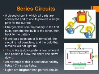
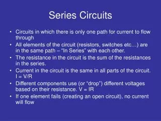
Series Circuit • More than one resistor in a single path • Each electron must go through every resistor • Total resistance increases with every resistor added in series
Current in a Series Circuit • Current flow depends on all resistors • Current through each resistor is the same IT = I1 = I2 = … R1 R2
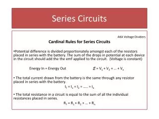
Remember, Voltage is Lost in Resistors • A voltage exists across every device (voltage supply, resistors, light bulbs, etc.) • As an electron goes through a resistor or device it loses energy because it does work to get through • How much energy lost per Coulomb (voltage) depends on the resistance
Voltage in a Series Circuit • Voltage gained by electrons when leaving the voltage supply equals the total voltage lost before returning • Since voltage is lost through all resistors VT = V1 + V2 + … R1 R2
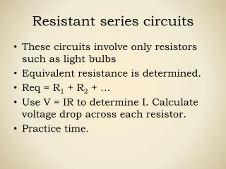
Total Resistance in a Series Circuit To determine the current leaving the voltage supply the total resistance must be used RT = R1 + R2 +… R1 R2
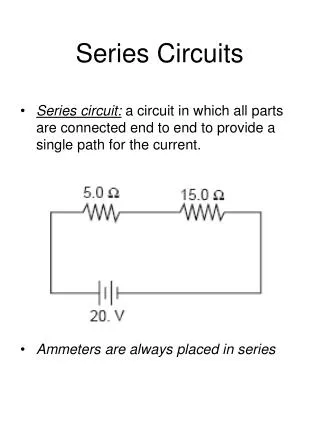
Analyzing a Series Circuit Determine the total current in the circuit V = IR 12 V = I(24 Ω) I = 0.5 A 10 Ω 12 V RT = R1 + R2 = 10 Ω + 14 Ω = 24 Ω 14 Ω
Analyzing a Series Circuit Determine the voltage in the 10 Ω resistor V = IR V= 0.5 A(10 Ω) V = 5 V 10 Ω 12 V 14 Ω
Analyzing a Series Circuit Determine the voltage in the 14 Ω resistor V = IR V= 0.5 A(14 Ω) V = 7 V 10 Ω 12 V or VT = V1 + V2 12 V = 5 V + V2 V2 = 7 V 14 Ω
Comparing Circuits with Series Resistors A B 5 Ω 5 Ω 5 Ω 12 V 12 V 5 Ω 5 Ω By adding another resistor in series Increase total resistance Decreases current Voltage across each resistor decreases
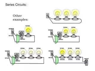
Resistors in Series • Adding a resistor in series increases the total resistance • When one resistor is disconnected the circuit is open – current does not flow • Everyone has to go through all doors to get out • The smallest door slows the movement the most