Download
1 / 9
150 likes | 466 Views
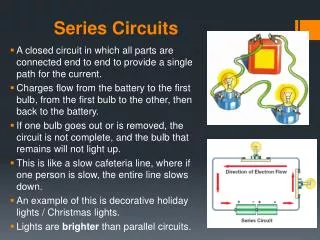
Series Circuits. Series circuit: a circuit in which all parts are connected end to end to provide a single path for the current. Ammeters are always placed in series. The current is the same through each resistor I = I 1 = I 2 = I 3 ….

E N D
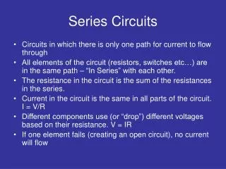
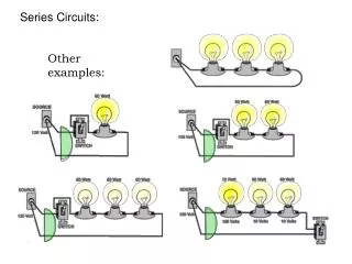
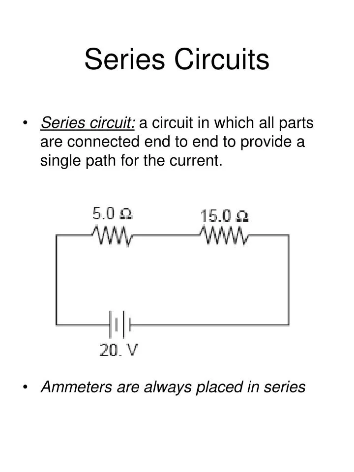
Series Circuits • Series circuit: a circuit in which all parts are connected end to end to provide a single path for the current. • Ammeters are always placed in series
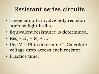
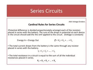
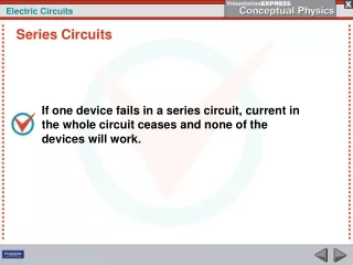
The current is the same through each resistor • I = I1 = I2 = I3 …. • The total potential difference equals the sum of the potential differences across the individual resistors. • V = V1 + V2 + V3 …. • Equivalent resistance: resistance of a single resistor that could replace a combination of resistors • Req = R1 + R2 + R3 ….
Example: Four 15 Ω resistors are connected in a series to a 45-V battery. a.) Draw the circuit (include an ammeter and voltmeter) b.) What is the current of the circuit? c.) What is the potential difference across each resistor? Example: A 5.0Ω resistor and a 10.0 Ω resistor are connected in series and placed across a 45.0-V potential difference. a.) Draw the circuit (include an ammeter and voltmeter) b.) What is the equivalent resistance of the circuit? c.) What is the current through the circuit? d.) What is the voltage drop across each resistor? Example: A 20.0Ω light bulb and a 5.0 Ω light bulb are connected in series and placed across a potential difference of 50.0 V. a.) Draw the circuit (include an ammeter and voltmeter) b.) What is the equivalent resistance of the circuit? c.) What is the current in the circuit? d.) What is the voltage drop across each light bulb? e.) What is the power through each light bulb?
Parallel Circuits • parallel circuit: circuit that has multiple independent paths along which the current can flow . Each component has its own path • Voltmeters are always placed in parallel.
The sum of the currents in the branches is equal to the total current from the source • I = I1 + I2 + I3 …. • the potential difference across each branch of the parallel circuit is the same as that of the potential difference supplied by the source • V = V1 = V2 = V3 …. • the equivalent resistance is always less than the resistance of any branch • 1/Req =1/ R1 + 1/R2 + 1/R3 …. • Note: Find a common denominator or use a calculator. • The resistance decreases because each new resistor provides an additional path for current to flow.
When appliances are connected in parallel, each additional appliance placed in operation reduces the equivalent resistance in the circuit and causes more current to flow through the wires. • fuses a short piece of metal that melts from the heating effect of the current, breaks the circuit if too much current is flowing, this can prevent damage and fire • A circuit breaker is an automatic switch that opens when the current reaches some set value. Doesn’t need to be replaced. • Short circuit: occurs when a circuit is formed that has a very low resistance. The low resistance causes the current to be very large. If there were no fuse or circuit breaker, such a large current could easily start a fire.
Kirchoff’s 1st law (Conservation of charge in electric circuits): Charge in an electric current must be conserved. At any junction in a circuit, the sum of the currents entering the junction must equal the sum of the currents leaving it.
Example: Three resistors of 60.0 Ω, 30.0 Ω, and 20.0 Ω are connected in parallel across a 90.0-V difference in potential. a.) Draw the circuit (include an ammeter and voltmeter) b.) Find the equivalent resistance of the circuit. c.) Find the current in the entire circuit. d.) Find the current through each branch of the circuit. • Example: A 20.0 Ω lamp and a 50.0 Ω lamp are connected in parallel and placed across a difference in potential of 50.0-V. a.) Draw the circuit (include an ammeter and voltmeter) b.) What is the equivalent resistance of the circuit? c.) What is the current of the circuit? d.) What is the current through each resistor? e.) What is the voltage drop across each resistor? f.) What is the power used by each lamp?
Example: A 16.0 Ω and a 20.0 Ω resistor are connected in parallel. A difference in potential of 40.0V is applied to the circuit. a.) Draw the circuit (include an ammeter and voltmeter) b.) Compute the equivalent resistance of the circuit? c.) What is the current of the circuit? d.) What is the current through each resistor?