1 / 0

Resistant series circuits

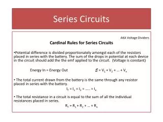
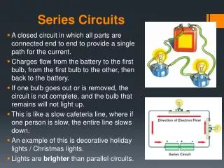
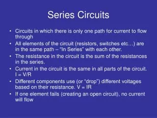
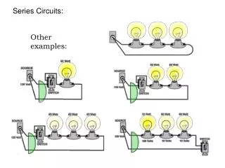
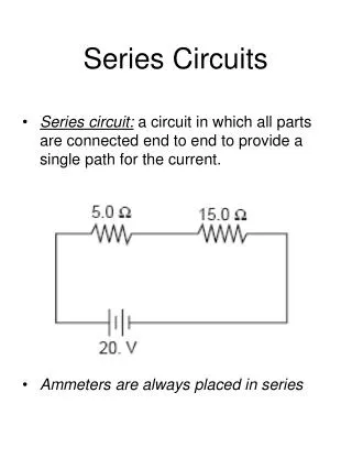
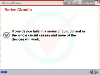
Resistant series circuits. These circuits involve only resistors such as light bulbs Equivalent resistance is determined. Req = R 1 + R 2 + … Use V = IR to determine I. Calculate voltage drop across each resistor. Practice time. Series circuits. Resistant parallel circuits.

derry
Download Presentation

Resistant series circuits

An Image/Link below is provided (as is) to download presentation Download Policy: Content on the Website is provided to you AS IS for your information and personal use and may not be sold / licensed / shared on other websites without getting consent from its author. Content is provided to you AS IS for your information and personal use only. Download presentation by click this link. While downloading, if for some reason you are not able to download a presentation, the publisher may have deleted the file from their server. During download, if you can't get a presentation, the file might be deleted by the publisher.

E N D

Presentation Transcript


  1. Resistant series circuits These circuits involve only resistors such as light bulbs Equivalent resistance is determined. Req = R1 + R2 + … Use V = IR to determine I. Calculate voltage drop across each resistor. Practice time.
  2. Series circuits
  3. Resistant parallel circuits These circuits involve only resistors such as light bulbs Equivalent resistance is determined. 1/Req = 1/R1 + 1/R2 + … Use V = IR to determine I. Calculate voltage drop across each resistor. Practice time.
  4. Parallel circuits
  5. Series RC circuits Equivalent resistance and capacitance is determined. Req = R1 + R2 + … 1/Ceq = 1/C1 + 1/C2 + … Use V = IR to determine I. Calculate voltage drop across each resistor. Use q = CV and divide by time to get current. We will not do this since current changes. Practice time.
  6. Parallel RC circuits Equivalent resistance and capacitance is determined. 1/Req = 1/R1 + 1/R2 + … Ceq = C1 + C2 + … Use V = IR to determine I. Calculate voltage drop across each resistor. Use q = CV and divide by time to get current. We will not do this since current changes. Practice time.
  7. Complex circuits Use same principles to isolate one equivalent resistance and reverse engineer solution to circuit. Lots of practice time to follow.
  8. Kirchoff’s laws Voltage Law: The sum of all of the voltages around any closed loop must equal 0. Current Law: The sum of all currents in any node must equal 0. These may be used to help solve complex circuits.
  9. Silicon chips Silicon has no free electrons and makes a very good insulator. Its large atomic radii make it ideal for doping.
  10. Silicon doping N type semiconductors have phosphorus or arsenic put in the silicon matrix. With 5 electrons, they provide one unbonded electron each. P type semiconductors have boron or gallium put in the silicon matrix. With only 3 electrons, they result in a deficiency of electrons, or a hole.
  11. Silicon doping No current flows this way. If we reverse the battery, what happens?
  12. Silicon doping Transistors use 3 layers of doped silicon, and can be PNP or NPN types. Current will not flow unless you apply a small current to the center section, in which case it amplifies the current flow. Transistors allowed the creation of the silicon chip and the microprocessor used in computers.
  13. PNP transistor
  14. Transistor images
  15. How are transistors used? To switch electronic signals between on and off positions. This is a simple logic circuit. To amplify the signal obtained. These are used in radios, TV’s, etc to produce volume.
More Related