Download
1 / 18
180 likes | 315 Views
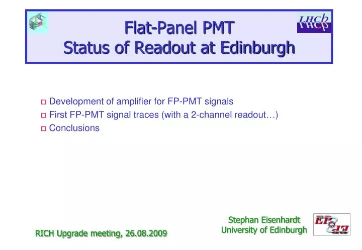
Flat-Panel PMT Status of Readout at Edinburgh. Development of amplifier for FP-PMT signals First FP-PMT signal traces (with a 2-channel readout…) Conclusions. Stephan Eisenhardt University of Edinburgh. RICH Upgrade meeting, 2 6.08.2009. Task: Build a Reference Readout .

E N D
Flat-Panel PMTStatus of Readout at Edinburgh Development of amplifier for FP-PMT signals First FP-PMT signal traces (with a 2-channel readout…) Conclusions Stephan Eisenhardt University of Edinburgh RICH Upgrade meeting, 26.08.2009
Task: Build a Reference Readout . • Adapt signal output of FP-PMT to charge sensitive ADCs need 64x amp: gain ~100 PMT signal: 0.06 – 0.24pC (0.375 – 1.5 Me-) 256 channels ADC Range: 0 – 400pC Resolution: 0.10pC 2x32 channels Stephan Eisenhardt
How to … • Commercial fast amps too expensive for 64 channels: • channel gain: 10 • e.g. 16 channels for ~ £ 3000.- • OK for 8 channels, as done for MaPMT • too expensive for 64 channels ( = £ 24000.-) • Alternative : build your own… • large gain • low noise • linear in charge amplification • fast (base of pulse shape <15ns) Stephan Eisenhardt
Our Solution • Base: op-amp LMH 6702 • non-differential, wideband op-amp • ultra low distortion • bandwidth at gain 2: 1.7GHz (output signal <0.5Vpp) • bandwidth at gain 10: 370MHz • operated in inverting mode • fast slew rate: 3100V/ms • low noise: 1.83nV/ Hz • Our layout: • two-stage amplifier • 50W input and output termination • each stage with gain 10 operation outside recommended range… • strong noise filtering • signal GND and power GND separated Stephan Eisenhardt
Biasing • Restriction by the input circuit of the V792: may not exceed +15mV • risk of damage to the input circuit • i.e. positive overshoots may kill the expensive devices… • Solution: • adjustable bias circuit in the output • capacitive decoupling (100nF) • bias adjustable (0…-5V) • use low noise trimmer (500W, 25 turn) • Operation: • mandatory study of output signals before connecting to V792 • set biases for all channels individually to a safe value… Stephan Eisenhardt
The Prototype • Built and studies by Iain Longstaff (summer student): • using two evaluation PCBs • signal source: MaPMT@1000V gain ~1.2Me- (centre channel) • use dark counts = single photoelectrons • signal split to: - amp input - oscilloscope • readout: oscilloscope 50W input Stephan Eisenhardt
MaPMT Signal Trace MaPMT pulses 10mV/div amp pulses 500mV/div time scale 4ns/div >2000 pulses Stephan Eisenhardt
Prototype Results • Voltage gain: • saturates: at 4V - bias • due to output current limit of 80mA & 50W termination • Charge gain: • effective gain: expected: 142, found: 132±3 • linear over the whole spectrum, if integrated over 16ns • Noise: • measured standard deviation of pedestal (HV of MaPMT off) • std dev @ input: 0.58mV • std dev @ output: 19mV • ratio: 33 << gain • noise at input limited by measurement, not by amplifier 400pC 1pC Stephan Eisenhardt
Amplifier Status • Single Channel amplifier PCB: • PCB designed • 130 PCBs produced • first PCB populated and under test • Motherboard: • currently in PCB design • 64 amplifier PCBs plug vertically in • alternating from front and back side • same input track length (capacity!) • impedance match where possible • power bus bars • 64 biasing circuits • complication: high density input connector • 2x40 pins, 0.75 mm pitch • connecting to both sides of the PCB • connecting to GND on the edge amp circuit GND planes 4 output connectors a 16 ch 64 ch input connector room for bias circuits Stephan Eisenhardt
Two-Channel Readout • How to read out single FP-PMT channels? (without a proper setup…) • need proper grounding of other channels… • Recipee: • use 4 PCB mount connectors • roll copper foil • squeeze between solder pins (shorts 16 GND to 64 signal pins) • leave gap to feed out 2 channels… Stephan Eisenhardt
Two-Channel Readout • feed lines directly into LEMO cables… • and ground well (aehm, sort off…) • prop up FP-PMT in dark box • and look for dark counts • caveat: no cross-talk study possible yet (not neighbouring channels) Stephan Eisenhardt
FP-PMT Signal Trace FP-PMT pulse 10mV/div amp pulse 500mV/div time scale 4ns/div trise~0.8ns 1 pulse Stephan Eisenhardt
MaPMT Signal Trace known reflection from Y-split MaPMT pulse 10mV/div time scale 4ns/div amp pulse 500mV/div trise~1.2ns 1 pulse Stephan Eisenhardt
FP-PMT Signal Trace FP-PMT pulses 10mV/div amp pulses 500mV/div time scale 4ns/div >1000 pulses Stephan Eisenhardt
FP-PMT Signal Trace FP-PMT pulses 10mV/div amp pulses 500mV/div time scale 10ns/div >1000 pulses Stephan Eisenhardt
FP-PMT Signal Trace FP-PMT pulses 10mV/div amp pulses 500mV/div time scale 40ns/div >1000 pulses Stephan Eisenhardt
Conclusions • Amplifier development took longer than expected (not aided by me being ill for >1 month…) • Prototype amplifier works very well • linear in charge amplification • large gain • low noise • PCB status • amplifier PCB just back from production • motherboard PCB on the drawing board • FP-PMT signal trace • fast signal indeed: trise ~0.8ns as in data sheet • ringing on the trace: not yet understood Stephan Eisenhardt
Spare Slides Stephan Eisenhardt