Download
1 / 18
180 likes | 188 Views
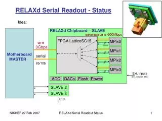
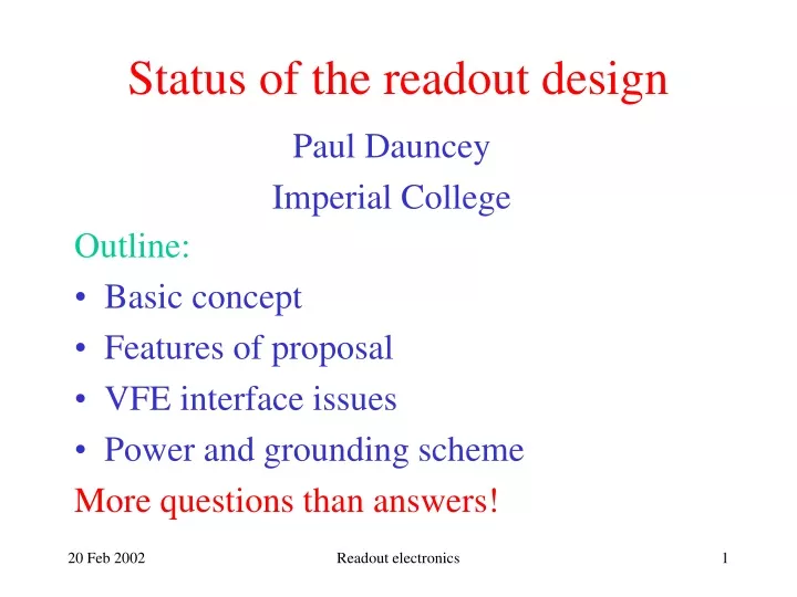
Status of the readout design. Paul Dauncey Imperial College. Outline: Basic concept Features of proposal VFE interface issues Power and grounding scheme More questions than answers!. Basic concept. Want to run close to “TESLA mode”: Learn how to operator at collider

E N D
Status of the readout design Paul Dauncey Imperial College Outline: • Basic concept • Features of proposal • VFE interface issues • Power and grounding scheme More questions than answers! Readout electronics
Basic concept Want to run close to “TESLA mode”: • Learn how to operator at collider • Looks like innovative LC R&D; more chance of funding Operate according to “bunch trains”: • Timing set by TESLA parameter; not necessarily related to beam timing • Store digitised data near front end and read out after train; demonstrate untriggered running Readout electronics
Basic concept (2) TESLA train is 2820 bunches, 337 ns apart @ 5Hz • 337 ns is ~ 3 MHz • Readout ADC’s will sample at this rate • Particle signal appears for one sample only • Maximum clock needed is 16 x 3 MHz = 48 MHz • 2820 bunches is ~ 1ms • Readout allows up to 4096 bunches • Would a maximum of 2048 bunches (~ 0.7 ms) be a significant issue? • Ignor 5 Hz repetition rate Readout electronics
Overview of readout • Front end card (FEC) connects to VFE chip • Link interface card (LIC) does electrical-optic conversion “on-detector” • Back end card (BEC) interfaces to PC. Readout electronics
Front end card (FEC) • One FEC handles 3 silicon wafers = 7 VFE chips = 108 channels (has 112 = 7x16 channels). Results in 90 FEC’s in total. • VFE chips mounted on daughterboard(s); need to think about interface here (later) • All power and ground routed through FEC. Readout electronics
Front end card (2) Features • ADC’s sample VFE output at 12 MHz to allow for up to four gain ranges to be used • Large memory stores raw data and small memory stores data after threshold cut; either or both can be read out. • On-board DAC to generate calibration pulse • All timing adjustments software configurable to a 48 MHz scale (21 ns). Readout electronics
Link interface card (LIC) • One LIC handles 15 FEC’s (5 layers). Results in 6 LIC’s in total • Clock and control on uplink sent to all 15 FEC’s; data from same FEC’s on downlink. • Power and ground routed through LIC. Readout electronics
Back end card (BEC) Not so well defined: • Functionally simple • To uplink: clock (from fast control) and StartTrain or PC commands to FEC’s • From downlink: data from FEC’s to memory and then to PC • Implementation not so obvious • Several options being considered • Sketch out one; VME system where this functionality is split over two physical cards Readout electronics
BEC driver • One BEC driver handles all 6 LIC’s. • Clock and control distributed from here • Interfaces to fast control and VME for PC control Readout electronics
BEC receiver • One BEC receiver handles 30 FEC’s = 2 LIC’s. Results in 3 BEC receivers in total. • Buffers readout data until read by VME • Checks FEC’s are still synchronised after train Readout electronics
BEC options Other possibilities are: • CompaqPCI crate rather than VME • Similar but maybe cheaper; can this be combined with HCAL readout? • Implement on PCI cards • Plug into PC bus directly; no crate • Restricted by small size; need to rethink data handling as memories will not fit • Interface BEC’s directly to network • TPC/IP interface; send data to disk as IP packets. Readout electronics
Data readout rates • Noise above threshold ~ 0.1% (3s) ~ 10 channels per sample ~ 30000 per train • Showers ~ 1800 samples per shower ~ 7 kBytes • Readout mainly limited by VME ~ 25 MBytes/s • Shower readout at ~kHz should be possible. • How much data do we expect? TBytes? Readout electronics
VFE daughterboard interface Important to be sure we agree at VFE-FEC. We assume the VFE daughterboard needs: • Sample-and-hold clock and gain range clock • Power and ground • Calibration signals We assume it gives out: • Differential analog signal per channel; what are the voltage levels? Readout electronics
VFE daughterboard interface (2) Clocks; send differential digital, suggest LVDS: • 3 MHz sample-and-hold clock • 12 MHz gain range clock; max of 4 gains • Phase of these (and ADC’s) adjustable to 21 ns Power and ground: • Power for VFE chips themselves; what voltages and power consumption? • Bias voltage for silicon diodes; ditto? • Separate analog and digital power and ground? Readout electronics
VFE daughterboard interface (3) Calibration: • Will calibration pulses go to diodes, VFE inputs or both? Multiple capacitors? Selectable? • Channel selection, digital TTL. What granularity; any possible combination of channels? • 16-bit configurable DAC on FEC; sets constant analog level; same for all channels on FEC. Differential; what voltage range and polarity? • Time of single pulse set by digital signal; LVDS. Configurable to a 48 MHz tick; fine enough? Readout electronics
VFE daughterboard interface (4) Pin count seems reasonable: • Analog signals = 32 pins/VFE chip • Calibration selection = 16 pins/VFE chip • Calibration analog voltage = 2 pins • Clocks and calibration time = 6 pins • Power and ground = 8 pins (?) Implies 64-pin connector per VFE chip: • All 7 VFE chips on one daughterboard? • Each VFE chip on its own daughterboard? Readout electronics
Power and grounding This scheme routes all power out, and grounds back, in a “tree” configuration: • Power supply (who buys this?) to all 6 LIC’s • Each LIC to 15 FEC’s • Each FEC to 7 VFE chips and 3 wafers Requires no grounding of diodes or VFE chips elsewhere to avoid ground loops: • Must have no electrical contact to carbon fibre support structure; is this possible/desirable? Readout electronics
Summary • We think we have a feasible system: • Need to firm it up over next few weeks to submit proposal • After that, major system changes will be very difficult (unless cheaper!) • We need a lot of information (soon) to cost it properly: • How and when do we get the answers we need? • Are some of them known already? Readout electronics