Download
1 / 19
190 likes | 323 Views
PMT Support Structure. STATUS. Enrique Calvo Alamillo Chooz - 26 June 2008. INDEX:. Gamma-catcher and target vessel tools manufacture. Final PMT distribution in the detector. Final design of PMT supports. Mechanical devices to machine/weld the different fixation points on the buffer.

E N D
PMT Support Structure.STATUS. Enrique Calvo Alamillo Chooz - 26 June 2008
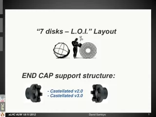
INDEX: • Gamma-catcher and target vessel tools manufacture. • Final PMT distribution in the detector. • Final design of PMT supports. • Mechanical devices to machine/weld the different fixation points on the buffer. • Status of acrylics and stainless steel production. • Schedule of supports production, treatment, cleaning and delivery. • Next Steps. Double-Chooz Collaboration meeting (Chooz)
Gamma-catcher and target vessel tools manufacturing. • (built at CIEMAT workshop) At Madrid 4 different kind of tools were built following the drawing supplied by Saclay. All tools were sent to Saclay: To produce those we had 3 people working full time during several months . • One tool unit for the gamma catcher and two rotation units. • Three tool units for the target. • One tool unit for the transport. Double-Chooz Collaboration meeting (Chooz)
2. Final PMT distribution in the detector. This is the last approved distribution. That was simulated by Glenn. The positioning precision of the PMTs will be approximately +- 1 cm and +- 1º. The orientation of the PMTs on the lids is towards the center. On the cylinder PMT are not pointing to the center. Double-Chooz Collaboration meeting (Chooz)
3. Final design of PMT Support Structure. • PMT Assembly. This is the last approved PMT assembly. Composed for 1.4 kg of Acrylic and 1.1 kg of magnetic shielding. Total weight of different material on the detector is aprox: -Acrylic………………….541 kg. Inox screws………………….20 kg. -Magnetic shielding……440 kg. Nylon 6.6 screws……………25 kg. -Inox 304 L……………..459 kg. Nylon clamp………………….15 kg. Double-Chooz Collaboration meeting (Chooz)
PMT Support Structure. • Sector of PMTs distribution on the buffer. • Shown the Detector axis directions, respect of the center. • X toward the exit of the cavern. (Longitudinal axis of the cavern) • Y transversal axis of the cavern. • Z vertical axis. Double-Chooz Collaboration meeting (Chooz)
PMTs distribution on the top LID. Double-Chooz Collaboration meeting (Chooz)
Z Z x Y PMTs distribution on the cylindrical buffer sector. Double-Chooz Collaboration meeting (Chooz)
PMTs distribution on the bottom LID. Double-Chooz Collaboration meeting (Chooz)
Y X Top and lateral view of one of six sectors. Double-Chooz Collaboration meeting (Chooz)
Top and Bottom fixation structure on the buffer lids. This structure is composed by 2 central rings and 3 sector of circles. Attached to some pieces welded to the buffer wall. The PMTs are fixed to this structure by 2 M6 screws on each side. Double-Chooz Collaboration meeting (Chooz)
Cylindrical fixation structure on the buffer. This structure is composed by 30 circumferential sectors of two independent vertical L profiles, distributed on 3 vertical step. Those are attached to the buffer circumferential reinforces by M6 holes on both extremes of the profile. The PMTs are fixed on the L profiles by 2 M6 screws on each side. Double-Chooz Collaboration meeting (Chooz)
Bottom Top 4. Mechanical devices to machine/weld the different fixation points on the buffer. Both tools was sent to Saclay. • Tool to drill the holes on the cylindrical buffer wall. • This will allow to drill the holes on the buffer wall to fix the vertical L profiles within the needed tolerance. • Tool to weld the pieces on the Lids. • Will allow to position the pieces to be welded, to mount the rings and circular sectors on. To weld the pieces on top or bottom it is necessary change 6 pieces on the second ring. Double-Chooz Collaboration meeting (Chooz)
5. Status of acrylics and stainless steel production. To build those we have 11 people working full time from 3 moths and 4 to clean the pieces. • The acrylic pieces: The 7 different kind of acrylic pieces production is well advanced. 840 to build. Built 834 Cleaned 831 1640 to build. Built 1359 Cleaned 1343 1640 to build. Built 1376 Cleaned 866 840 to build. Built 560 Cleaned 327 420 to build. Built 278 Cleaned 137 1680 to build. Built 855 Cleaned 849 420 to build. Built 419 Cleaned 415 Double-Chooz Collaboration meeting (Chooz)
12 to build (top). 6 to build (top). • The Inox pieces: • There are 17 different inox pieces to produce. The fabrication is under progress. 6 to build (bottom). 12 to build (bottom). 36 to build. 48 to build. 60 to build. 60 to build. 60 to build. 60 to build. 30 to build. Double-Chooz Collaboration meeting (Chooz)
The support structure: There are 16 different inox pieces to produce. The fabrication is under progress. • On cylinder Buffer 65+65 to build. 32+32 to build. Double-Chooz Collaboration meeting (Chooz)
1 assemblies to build (top). • On lids Buffer 6 to build. 126 to build. 140 built. 1 assemblies to build (bottom). 12 assemblies to build. Double-Chooz Collaboration meeting (Chooz)
6. Schedule of supports production, treatment, cleaning and delivery. • The acrylic pieces: All acrylic pieces that compound the PMT assembly will be ready to be delivered to Heidelberg during July. • The Inox pieces: All inox pieces to fix the PMT assembly to the support structure will be ready to be delivered to Chooz during September. • The support structure: All inox support pieces will be ready to be delivered to Chooz during September. Except the pieces to weld on the buffer that were delivered to Saclay. Double-Chooz Collaboration meeting (Chooz)
7. Next Steps. • Include the magnetic probes and Led-fibers on the 3D models. The installation of those devices and cables/OF should be integrated on the installation of the buffer PMTs and installed at the same time. • Include on the 3D the different orientations of the PMT cables exit. • Update the TDR with the new PMT distribution and final PMT support • Update TDR with the assembly procedure for the PMTs support/assembly pieces. • Detailed installation process of the PMTs on the buffer. • Define the tooling necessary for those Jobs. • Define space, time and man-power requirements to do previous tasks . Double-Chooz Collaboration meeting (Chooz)