Download
1 / 19
190 likes | 373 Views
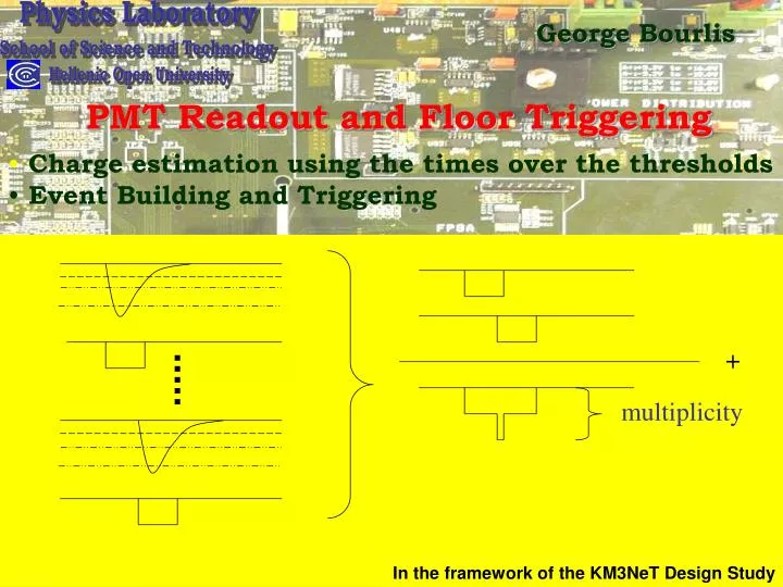
Physics Laboratory. School of Science and Technology. Hellenic Open University. +. multiplicity. George Bourlis. PMT Readout and Floor Triggering. Charge estimation using the times over the thresholds Event Building and Triggering. In the framework of the KM3NeT Design Study.

E N D
Physics Laboratory School of Science and Technology Hellenic Open University + multiplicity George Bourlis PMT Readout and Floor Triggering • Charge estimation using the times over the thresholds • Event Building and Triggering In the framework of the KM3NeT Design Study
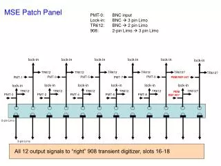
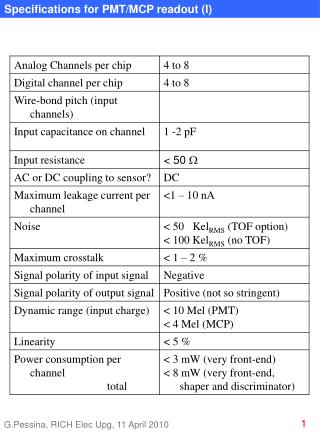
ReadOut Electronics 5 PMT Signal Inputs Trigger Output USB Port • HPTDC • 32 channels (LR) – 8 Channels (HR) • 25ps (HR) to 100 ps (LR) accuracy • Self Calibrating 25ps accuracy TDC GPS Input
Input Trigger Time (ns)
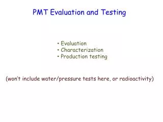
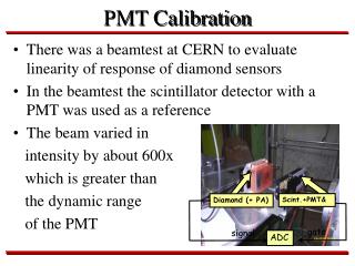
@ “nominal” H.V. gain: ~ 4 105 <charge>/p.e. ~ 0.07pCb <pulse height>/p.e. ~ 1.05mV Rise Time: 1.2 ns Single p.e At the Detector Center • Data - Monte Carlo Prediction Charge (pCb) Charge (in units of mean p.e. charge) The Photomultiplier Tube: PH: XP1912 Gain vs HV Calibration
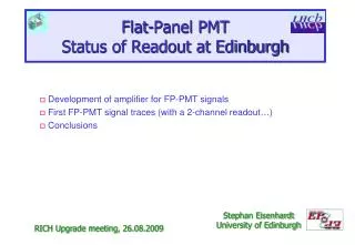
Charge (pC) 1st Threshold only 1st, 2nd & 3rd Threshold 1st & 2nd Threshold Time Over Threshold (s) Charge versus Time Over Threshold 50mV 15mV 4mV
Charge Parameterization 1st & 2nd Threshold 1st, 2nd & 3rd Threshold
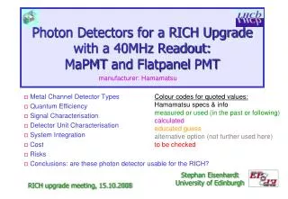
11% 8% Charge Estimation 1st & 2nd Threshold 1st, 2nd & 3rd Threshold - Estimated Resolution ~10% - Better if all thresholds are crossed
Charge Estimation 1st & 2nd Threshold 1st, 2nd & 3rd Threshold - σ=(1.01 ± 0.01) (2 thresholds) - σ=(1.1 ± 0.1) (3 thresholds)
HPTDC architecture HPTDC is fed by a 40 MHz clock giving us a basic 25 ns period (coarse count). A PLL (Phase Locked Loop) deviceinside the chip does clock multiplication by a factor 8 (3 bits) to 320 MHz (3.125 ns period) . ADLL (Delay Locked Loop)done by 32 cells fed by the PLL clock acts a 5 bits hit register for each PLL clock (98 ps width LSB = 3.125 ns/32). 4R-C delay linesdivides each DLL bin in 4 parts (R-C interpolation) in high resolution (25ps) mode.