Download

1 / 42
420 likes | 570 Views
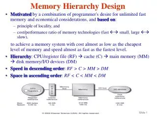
MEMORY in 80X86 Design. Outline. Addressing memory Data types MOV instruction Addressing modes Instruction format. Basics. Memory in the x86 processors is byte-addressable Whenever we present an address to the address bus, we specify the location of a byte in memory

E N D
Outline • Addressing memory • Data types • MOV instruction • Addressing modes • Instruction format
Basics • Memory in the x86 processors is byte-addressable • Whenever we present an address to the address bus, we specify the location of a byte in memory • Byte is the basic memory unit • It is possible to retrieve/store more than one bytes with a single memory access • 16-bit words, consecutive bytes • 32-bit doublewords, consecutive bytes
Logical vs. physical memory • Logical memory is the “view” of memory seen by the programmer • A large byte-addressable array of bytes • We can read/write bytes, words or doublewords • We do not worry about how data is fetched from memory, we only see the result of the memory access as 1,2, or 4 bytes • Physical memory • The physical organization of memory cells, which is not “visible” to the programmer • The unit of access to physical memory is equal to the width of the data bus • E.g. 16 bits in 8086, 32 bits in 80386 and later
8086 physical memory • Read a byte of address 0: result=FF • Read a word from address 0: result=ABFF • Read a doubleword from address 0: result=5512ABFF Odd Bank Even Bank F E 90 87 D E9 11 C B F1 24 A 9 01 46 8 7 6 76 DE 5 14 33 4 3 55 12 2 1 AB FF 0 Data Bus (15:8) Data Bus (7:0)
x86 byte ordering • Memory locations 0 and 1 contain FF and AB… • But a word access from address 0 returns ABFF • x86 uses “little endian” byte order • The requested address (0) points to the lower order byte of the result • The higher order byte of the result is taken from the next higher sequential address (1)
Byte ordering • Little endian vs. big endian • In big endian ordering the higher order byte of the result is retrieved from the requested address • Used in many UNIX servers • Byte ordering is a property of the architecture
Byte alignment • When we read from word 0 data(15:8)=AB,data(7:0)=FF • Bytes as presented in the data bus are in the right order! • This is an aligned memory access Odd Bank Even Bank F E 90 87 D E9 11 C B F1 24 A 9 01 46 8 7 6 76 DE 5 14 33 4 3 55 12 2 1 AB FF 0 Data Bus (15:8) Data Bus (7:0)
Byte alignment • What if read a word from address 1 ? • It is a valid memory access, you can always read from odd addresses • Result should be 12AB • But the bytes in the data bus are not aligned data(15:8)=AB,data(7:0)=12 Odd Bank Even Bank F E 90 87 D E9 11 C B F1 24 A 9 01 46 8 7 6 76 DE 5 14 33 4 3 55 12 2 1 AB FF 0 Data Bus (15:8) Data Bus (7:0)
Byte alignment • Whenever we read more than one bytes from memory the bytes presented in the address bus must be aligned according to the architecture byte ordering • If we read a word from address 1, the byte in address 2 must be stored in the higher order byte of the data bus and the byte in address 1 in the lower order byte of the data bus • 10 years ago I had to do that by hand… • But you don’t have to do it anymore, the processor takes care of it
Byte alignment • Do we have to worry about unaligned memory accesses ? • Yes, if you want your program to run fast! • In an unaligned memory access the processor has to • Read odd byte (one memory access) • Read even byte (second memory access) • Align the two bytes (some overhead in the hardware) • In an aligned memory access the processor just • Reads even byte (one memory access) • Aligned access is least twice as fast
Data Types • Integer numbers • Bits, Nibbles, Bytes, Words, Doublewords • Signed/unsigned • Floating point numbers • Different format than integers • Text • 7-bit ASCII characters (letters, characters) • 8-bit ASCII encoding allows for 128 more graphical symbols • Strings: sequences of characters • Documents: collection of strings
Data Types • Arrays • Sequences of numbers, characters • Files • Images (.jpg, .gif, .tiff,…) • Video (MPEG, .avi, Quicktime,…) • Audio (.wav, .mp3,…) • Everything is managed as a sequence of bytes stored in the memory of your computer! • The data type actually depends on the way you access and use these bytes!
Data Types • 16 signed/unsigned 8-bit integers • 8 signed/unsigned 16-bit words • 4 signed/unsigned 32-bit doublewords • An incomprehensible string… • Instructions and operands… Odd Bank Even Bank F E 90 87 D E9 11 C B F1 24 A 9 01 46 8 7 6 76 DE 5 14 33 4 3 55 12 2 1 AB FF 0 Data Bus (15:8) Data Bus (7:0)
Real vs. protected mode • In real mode we address the first megabyte of memory (00000h-FFFFFh), we are limited to a 20-bit address bus and 16-bit registers • In protected mode we can address 4 Gigabytes of memory using 32-bit address bus and 32-bit registers
Protected mode at a glance • Used in 80286 and higher • Memory accessing based on segmentation • Segments can be considered as “protected” regions of memory • Somehow more more complex address translation mechanism Contd…
Protected mode at a glance • Still segment:offset, segment is 16-bit, offset can be 16-bit or 32-bit • Segment field used as pointer to a segment table that contains the starting address of the segment in physical memory • You are not allowed to modify the segment table in user mode but you can in privileged mode, e.g. if writing an operating system
Using segments • Logical partitioning of your program Memory Original SP Used stack SS:BP SS:SP Unused stack SS Code (your program) CS:IP DS:DI Data (variables) DS:SI CS DS
The MOV instruction • Move data • From memory to a register • From a register to memory • From a register to another register • Never from memory to memory! • Syntax • MOV destination, source • Destination and source can be registers or memory addresses defined in different ways which we call “addressing modes”
Addressing modes • Register, the fastest! • MOV AX, BX • MOV AL, BL • MOV DX, SI • MOV DS, BX • Remember, source/destination must be of equal size • Immediate • Load a value to a register • MOV AX, 1234h
Addressing modes • Direct • MOV AX, [1234h] • Move data from a memory location to a register • 1234h is a displacement within the data segment DS • Register Indirect (base relative, or indexed) • MOV AX,[BX] • MOV AX,[BP] Contd…
Addressing modes • MOV AX,[SI] • MOV AX,[DI] • Displacement is put in a register • BX, SI, DI define displacements in the data segment • BP defines a displacement in the stack segment
Addressing modes • Base plus index (base relative indexed) • MOV AX, [BX+DI] • MOV AX, [BX+SI] • Base can be BX or BP, index SI or DI • Register relative • MOV AX, [BX+1234h] • Register on the left can be BX, BP, SI, or DI • Base relative plus index • MOV AX, [BX+DI+1234h]
How do I learn all this ? • All you have to remember is this table • Pick 0 or 1 item from each of the columns, just make sure you end up with at least one item • Never pick two items from the same column • 17 valid addressing modes BX SI DISP BP DI
Addressing mode examples Instruction Comment Addressing Mode Memory Contents MOV AX, BX Move to AX the 16-bit value in BX Register 89 D8 OP MODE MOV AX, DI Move to AX the 16-bit value in DI Register 89 F8 OP MODE MOV AH, AL Move to AL the 8-bit value in AX Register 88 C4 OP MODE MOV AH, 12h Move to AH the 8-bit value 12H Immediate B4 12 OP DATA8 MOV AX, 1234h Move to AX the value 1234h Immediate B8 34 OP DATA16 MOV AX, CONST Move to AX the constant defined as CONST Immediate B8 lsb msb OP DATA16 MOV AX, X Move to AX the address or offset of the variable X Immediate B8 lsb msb OP DATA16 MOV AX, [1234h] Move to AX the value at memory location 1234h Direct A1 34 12 OP DISP16 MOV AX, [X] Move to AX the value in memory location DS:X Direct A1 lsb msb OP DISP16
Addressing mode examples Instruction Comment Addressing Mode Memory Contents MOV [X], AX Move to the memory location pointed to by DS:X the value in AX Direct A3 lsb msb OP DATA16 MOV AX, [DI] Move to AX the 16-bit value pointed to by DS:DI Indexed 8B 05 OP MODE MOV [DI], AX Move to address DS:DI the 16-bit value in AX Indexed 89 05 OP MODE MOV AX, [BX] Move to AX the 16-bit value pointed to by DS:BX Register Indirect 8B 07 OP MODE MOV [BX], AX Move to the memory address DS:BX the 16-bit value stored in AX Register Indirect 89 07 OP MODE MOV [BP], AX Move to memory address SS:BP the 16-bit value in AX Register Indirect 89 46 OP MODE MOV AX, TAB[BX] Move to AX the value in memory at DS:BX + TAB Register Relative 8B 87 lsb msb OP MODE DISP16 MOV TAB[BX], AX Move value in AX to memory address DS:BX + TAB Register Relative 89 87 lsb msb OP MODE DISP16 MOV AX, [BX + DI] Move to AX the value in memory at DS:BX + DI Base Plus Index 8B 01 OP MODE
Addressing mode examples Instruction Comment Addressing Mode Memory Contents MOV [BX + DI], AX Move to the memory location pointed to by DS:X the value in AX Base Plus Index 89 01 OP MODE MOV AX, [BX + DI + 1234h] Move word in memory location DS:BX + DI + 1234h to AX register Base Rel Plus Index 8B 81 34 12 OP MODE DISP16 MOV word [BX + DI + 1234h], 5678h Move immediate value 5678h to memory location BX + DI + 1234h Base Rel Plus Index C7 81 34 12 78 56
Machine language • Everything (instructions, operands, data) is translated to bytes stored in memory • You need to be able to interpret the meaning of these bytes to debug your programs • In particular, we need to learn the format of instructions so that we can interpret the bytes that correspond to instructions in memory • x86 instructions are complex, they vary in size from 1 byte to 13 bytes
Generic instruction format Opcode Mode Displacement Data/Immediate No operands Example: NOP OP w/8-bit data Example: MOV AL, 15 OP DATA8 w/16-bit data Example: MOV AX, 1234h OP DATA16 w/8-bit displacement Example: JE +45 OP DISP8 w/16-bit displacement Example: MOV AL, [1234h] OP DISP16 w/mode – register to register Example: MOV AL, AH OP MODE w/mode & 8-bit displacement Example: MOV [BX + 12], AX OP MODE DISP8 w/mode & 16-bit displacement Example: MOV [BX+1234], AX OP MODE DISP16
Instruction Basics • Each instruction can have only one operand that points to a memory location • The sizes of the operands of an instruction must match • The mode byte encodes which registers are used by the instruction • If the data size used is ambiguous you have to specify it! • MOV BYTE [BX], 12h • MOV [BX], WORD 12h
D W Anatomy of an instruction Opcode Mode Displacement Data/Immediate • Opcode contains the type of instruction we execute plus two special bits, D and W • The mode byte is used only in instructions that use register addressing modes and encodes the source and destination for instructions with two operands OPCODE MOD REG R/M Contd…
Anatomy of an instruction • D stands for direction and defines the data flow of the instruction • D=0, data flows from REG to R/M • D=1, data flows from R/M to REG • W stands for the size of data • W=0, byte-sized data • W=1, word (in real mode) or double-word sized (in protected mode)
D W Anatomy of an instruction Opcode Mode Displacement Data/Immediate • MOD field specifies the addressing mode • 00 – no displacement • 01 – 8-bit displacement, sign extended • 10 – 16-bit displacement • 11 – R/M is a register, register addressing mode • If MOD is 00,01, or 10, the R/M field selects one of the memory addressing modes OPCODE MOD REG R/M
Registers in the REG and R/M fields Code W=0 (Byte) W=1 (Word) W=1 (DWord) 000 AL AX EAX 001 CL CX ECX 010 DL DX EDX 011 BL BX EBX 100 AH SP ESP 101 CH BP EBP 110 DH SI ESI 111 BH DI EDI
Example • Consider the instruction 8BECh • 1000 1011 1110 1100 binary • Opcode 100010 -> MOV • D=1 data goes from R/M to REG • W=1 data is word-sized • MOD=11, register addressing • REG=101 destination, R/M=100 source • MOV BP, SP Code W=0 W=1 W=1 000 AL AX EAX 001 CL CX ECX 010 DL DX EDX 011 BL BX EBX 100 AH SP ESP 101 CH BP EBP 110 DH SI ESI 111 BH DI EDI
Displacement addressing • If MOD is 00, 01, or 10 R/M has an entirely different meaning MOD FUNCTION 11 R/M is a register (register addressing mode) 00 No displacement R/M Code Function 01 8-bit sign-extended displacement 10 16-bit displacement 000 DS:BX+SI Examples: If MOD=00 and R/M=101 mode is [DI] If MOD=01 and R/M=101 mode is [DI+33h] If MODE=10 and R/M=101 modes is [DI+2233h] 001 DS:BX+DI 010 SS:BP+SI 011 SS:BP+DI 100 DS:SI 101 DS:DI 110 SS:BP 111 DS:BX
Code W=0 W=1 W=1 000 AL AX EAX 001 CL CX ECX 010 DL DX EDX 011 BL BX EBX 100 AH SP ESP 101 CH BP EBP R/M Code Function 110 DH SI ESI 111 BH DI EDI 000 DS:BX+SI 001 DS:BX+DI 010 SS:BP+SI 011 SS:BP+DI 100 DS:SI 101 DS:DI 110 SS:BP 111 DS:BX Example • Instruction 8A15h • 1000 1010 0001 0101 • Opcode 100010 -> MOV • D=1, data flows from R/M to REG • W=0, 8-bit argument • MOD=00 (no displacement) • REG=010 (DL) • REG=101 ([DI] addressing mode) • MOV DL, [DI]
Direct Addressing Mode • MOD is always 00 • R/M is always 110 • REG encodes the register to/from we take data as usual • Third byte contains the lower-order bytes of the displacement, fourth byte contains the high order byte of the displacement
Code W=0 W=1 W=1 000 AL AX EAX 001 CL CX ECX 010 DL DX EDX 011 BL BX EBX 100 AH SP ESP 101 CH BP EBP 110 DH SI ESI 111 BH DI EDI Direct Addressing • Example: 8816 00 10 • 1000 1000 0001 0110 0000 0000 0001 0000 • Opcode 100010 -> MOV • W=0 (byte-sized data) • D=0 data flows from REG • MOD 00, REG=010 (DL), R/M=110 • Low-order byte of displacement 00 • High-order byte of displacement 10 • MOV [1000h], DL
Oops • R/M=110 points to BP when MOD=00! • What happens with MOV DL, [BP] • No displacement, MOD=00 • [BP] addressing mode, R/M=110 • Hack… • MOV DL,[BP+0] • MOD=01 (8-bit displacement) • R/M=110 • This also means that MOV [BP] instructions are at least three bytes long (there is always a displacement even if it is 00)
R/M Code Function 000 DS:BX+SI 001 DS:BX+DI 010 SS:BP+SI 011 SS:BP+DI 100 DS:SI 101 DS:DI 110 SS:BP 111 DS:BX Immediate addressing • MOV WORD [BX+1000h], 1234h OPCODE W MOD R/M 1 1 0 0 0 1 1 1 1 0 0 0 0 1 1 1 Byte 1 Byte 2 Displacement-low Displacement-high 0 0 0 0 0 0 0 0 0 0 0 1 0 0 0 0 Byte 3 Byte 4 Data-low Data-high 0 0 1 1 0 1 0 0 0 0 0 1 0 0 1 0 Byte 5 Byte 6
Segment MOV instructions • Different opcode 100011 • Segments are selected by setting the REG field REG Code Segment reg. Example MOV BX, CS Opcode 10001100 MOD=11 (register addressing) REG=001 (CS) R/M=011 (BX) 8CCB 000 ES 001 CS 010 SS 011 DS 100 FS 101 GS