Download
1 / 25
290 likes | 485 Views
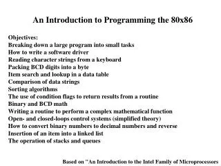
The Intel 80x86. Thorne : Section 1.4-1.6, 2.2.4, Section 3.4 (Irvine, Edition IV : Section 2.2). Getting to Know a Microprocessor. Any processor is characterized by its : Register Set General purpose, addressing, control/status registers Instruction set Includes addressing modes

E N D
The Intel 80x86 Thorne : Section 1.4-1.6, 2.2.4, Section 3.4(Irvine, Edition IV : Section 2.2) SYSC3006
Getting to Know a Microprocessor. • Any processor is characterized by its : • Register Set • General purpose, addressing, control/status registers • Instruction set • Includes addressing modes • Interrupt mechanism (later!) • We will study Intel 8086 which is the start of the 80x86 family tree. • All programming registers are 16-bit • 16-bit data bus and 20-bit address bus • I/O mapped with 8-bit and 16-bit ports (later) • Each descendant – right up to the P6 processor family – are backward compatible • Same basic set of registers … but wider • Same basic instructions … but more • Same interrupt mechanism SYSC3006
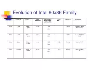
80x86 Family of Processors Like most texts, in Irvine and Thorne, you will encounter : Intel 8086 16-bit registers,16-bit data bus, 20-bit address bus Intel 80286 Same as 8086 but 24-bit address bus and “protected mode” IA-32 32-bit registers and data bus, 32-bit address bus P6 Extended and improved IA-32 architecture for performance Multitasking 20-bit address bus: up to 1M byte memory space (220) 24-bit 16M (224) 32-bit 4G (232) 36-bit 64G (236) SYSC3006
Modes of Operation • Real-Address Mode (DOS) • Microprocessor is acting like a 8086 • 1 Meg address space, 8086 instructions only, one program can run • Can access all memory and I/O hardware directly • Protected Mode • All instructions and features are available. • Multiple programs can run. Each program given separate memory areas (called segments) and CPU ensures accesses outside its segments are prevented. • Memory address is no longer “real”; within your program’s area • Virtual 8086 Mode • While running in Protected Mode, lets a program run in real-address mode • Running a DOS program under Windows (DOS command window) • …. But Windows prevents access to some addresses/hardware • This is the reason why we use DOS in this course. • Systems Management Mode • Provides an operating system that has functions for system security • Used by computer manufacturers to customize processors SYSC3006
1M-byte Memory Map of 8086 B. Brey, The Intel Microprocessors, 7th ed, 2006 SYSC3006
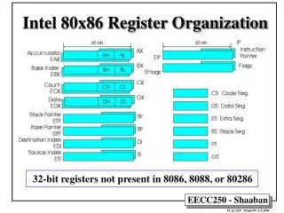
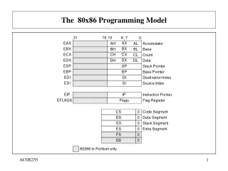
AH AL BH BL CH CL DH DL AH AL 8086 Register Set • 16-Bit General Purpose Registers • can access all 16-bits at once • can access just high (H) byte, or low (L) byte (Accumulator) (Base) (Count ) (Data) AX BX CX DX only the General Purpose registers allow access as 8-bit High/Low sub-registers 8-bit 8-bit For interested students : These registers in extended to 32-bits in the IA-32 family 16-bit EAX 32-bit SYSC3006
8086 Register Set 16-Bit Segment Addressing Registers CS Code Segment DS Data Segment SS Stack Segment ES Extra Segment 16-Bit Offset Addressing Registers SP Stack Pointer BP Base Pointer SI Source Index DI Destination Index SYSC3006
8086 Register Set 16-Bit Control/Status Registers IP: Instruction Pointer (Program Counter for execution control) FLAGS: 16-bit register • It is not a 16-bit value but it is a collection of 9 bit-flags (7 bits are unused) • Flag is set when it is equal to 1 • Flag is clear when it is equal to 0 Control Flags DF Direction Used in string instructions for moving forward/backward through string IF Interrupt Used to enable/disable interrupts (Later) TF Trap Used to enable/disable single-step trap (Later) • Flags register SYSC3006
8086 Register Set Status Flags (Arithmetic flag) • Flags are set and cleared as “side-effects” of an instruction • Part of learning an instruction is learning what flags is writes • There are instructions that “read” a flag and indicate whether or not that flag is set (1) or cleared (0). Status Flag Name CF Carry PF Parity AF Auxiliary Carry OF Overflow SF Sign ZF Zero SYSC3006
8086 Register Set • There are other registers that are part of the programmer’s model but are internal to the CPU • They support the execution of instructions • Example : IR Instruction Register • Example : ALU input/output registers are temporary registers (scratchpad values) • They cannot be accessed directly by programmers • May be larger than 16-bits SYSC3006
Registers in CPU Central processing unit (CPU) Bus interface unit (BIU) Execution unit (EU) SYSC3006
Intel Segmented Memory Model for 20-bit Address Space • Processor Design Problem: How can 16-bit registers and values be used to specify 20-bit addresses? • Want to use 16-bit registers to refer to memory addresses (e.g. for indirect addressing modes) ·One way: Use two registers “side-by-side” 20 bits 20 bits X X X X 0 0 0 X X X X X 0 X 8 bits 16 bits 16 bits 16 bits SYSC3006
Intel Segmented Memory Model for 20-bit Address Space • Real-Address Mode (8086 and not later family members) • On top of the linear address space (from 0 to 1 Meg-1), you can overlay a set of overlapping “segments” • Linear address space becomes known as the absolute address (20-bit value) • A segment is defined as a sequence of bytes that • Starts every 16-bytes • Every segment starts on an absolute address that ends in 0 (hex) Absolute address ↔ Segment:Offset Address offset : 2 bytes (16 bits) • Has a length of 64K consecutive bytes (64K = FFFFh) • Hints : 216 = 64K and all the 8086 registers are 16-bits wide SYSC3006
Intel Segmented Memory Model for 20-bit Address Space • Segment 0 starts at absolute address 00000H and goes to 0FFFFh • Segment 1 starts at absolute address 00010H and goes to 1000Fh (=0FFFFh+10h) • Segment 2 starts at absolute address 00020H and goes to 1001FH (=0FFFFh+20h) * Starts every 16-bytes (10h=16d) • A particular byte can be located by giving the segment numberand the offset within that segment. • A particular byte is located within more than one segment Segment i overlaps segment i + 1 SYSC3006
Intel Segmented Memory Model for 20-bit Address Space 00000H 00010H 00020H … 0FFFFh 1000Fh 1001Fh … n*00010 n*10H + 0FFFFh 20-bit Linear or Absolute Address Segment 0 Segment 1 Segment 2 … … Segment n SYSC3006
Intel Segmented Memory Model for 20-bit Address Space • At the hardware level : • An address is put on the Address Bus as a 20-bit linear address (absolute address) • From the Software (Programmer’s) Perspective: • Addresses are NEVER specified as 20-bit values • Addresses are ALWAYS specified as two 16-bit values : segment:offset • Who does the conversion ? • The CPU does the conversion (eg. during the fetch of an instruction) • As a programmer, you always use segment:offset (Recall segment addressing registers: CS, DS, SS, ES) SYSC3006
1M-byte Memory Map of 8086 B. Brey, The Intel Microprocessors, 7th ed, 2006 SYSC3006
s3 s2 s1 s0 o3 o2 o1 o0 o3 o2 o1 o0 Intel Segmented Memory Model for 20-bit Address Space • How does the CPU convert from segment:offset to absolute ? • Recall : Each segment starts at 16-byte boundary • Start address of a segment = segment number * 1610 • Hint : Is there a shortcut for multiplying by 16 when working in binary(hex) ? Segment→ Offset → determined by segment number 20-bit segment start address Segment * 10h→ s3 s2 s1 s00 offset Absolute Address a4 a3 a2 a1 a0 20-bit address SYSC3006
Intel Segmented Memory Model for 20-bit Address Space • Example: Suppose we have segment number = 6020H and offset = 4267H segment * 10H 60200 H + offset 4267 H 20-bit address 64467 H Absolute Address 20-bit address SYSC3006
Intel Segmented Memory Model for 20-bit Address Space • Remember : An Ugly Side Effect of Segmented Memory • Each memory byte can be referred to by many different SEG:OFS pairs • Example: The (unique) byte at address 00300 H can be referred to by: 0 H : 300 H 1 H : 2F0 H 30 H : 0 H ( more too ! ) SYSC3006
How is segmented memory managed by the 8086 ? • 8086 includes four 16-bit SEGMENT registers: • CS : Code Segment Register • DS : Data Segment Register • SS : Stack Segment Register • ES : Extra Segment Register • Segment registers are used by default as the segment values during certain memory access operations • All instruction fetches: CS : IP • “most” data access: DS : offset Since the processor uses contents of DS as the 16-bit segment value when fetching data, the programmer only needs to supply the 16-bit offset in instructions) BUT segments must be initialized before use (Later!) SYSC3006
Let’s refine the Instruction Execution Cycle … • Processor executes instruction by repeating: do { Fetch instruction: IR := mem[ CS:IP ] and adjust IP to point to nextsequential instruction Execute instruction in IR } until HLT instruction has been executed Notation := “gets loaded from” some interrupt stuff goes here ! more later! inherently sequential behaviour! SYSC3006
Let’s refine the Instruction Execution Cycle … • What is an instruction ? • On the Intel 8086, an instruction is a sequence of 1..6 bytes • We shall learn more about it later, but a simple (and incomplete) model of an instruction is as follows : • Common mistake : Do not apply little endian to an instruction. • Little endian only applies to word operations, not sequences of bytes. Byte 1 Byte 2 Byte 3 Byte 4 Byte 5 Byte 6 Opcode Operand Operand Operand Operand Operand Source if needed Destination Operand, if needed Tells what kind of instruction, How many bytes… SYSC3006
Let’s refine the Instruction Execution Cycle … Absolute (linear) address = CS * 10h + IP Before fetch: 00000 Processor 4B 13C08 3 bytes of instruction 13C09 36 FF 13C0A CS 1000 Address of “next” instruction 13C0B 4 bytes of next instruction IP 3C08 13C0E IR 07 43 A6 12 “previous” instruction FFFFF The first byte (opcode) of instruction tells the number of bytes to be fetched. SYSC3006
Let’s refine the Instruction Execution Cycle … After fetch: 00000 Processor 4B 13C08 3 bytes of instruction 36 13C09 FF CS 1000 13C0A 13C0B 4 bytes of next instruction IP 3C0B 13C0E IR 4B 36 FF “fetched” instruction FFFFF SYSC3006