Download
1 / 20
240 likes | 963 Views
Decoders. Now, we’ll look at some commonly used circuits: decoders and multiplexers. These serve as examples of the circuit analysis and design techniques from last lecture. They can be used to implement arbitrary functions.

E N D
Decoders • Now, we’ll look at some commonly used circuits: decoders and multiplexers. • These serve as examples of the circuit analysis and design techniques from last lecture. • They can be used to implement arbitrary functions. • We are introduced to abstraction and modularity as hardware design principles. • Throughout the semester, we’ll often use decoders and multiplexers as building blocks in designing more complex hardware. Decoders
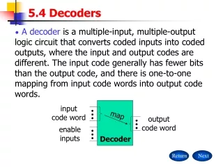
What is a decoder • In older days, the (good) printers used be like typewriters: • To print “A”, a wheel turned, brought the “A” key up, which then was struck on the paper. • Letters are encoded as 8 bit codes inside the computer. • When the particular combination of bits that encodes “A” is detected, we want to activate the output line corresponding to A • (Not actually how the wheels worked) • How to do this “detection” : decoder • General idea: given a k bit input, • Detect which of the 2^k combinations is represented • Produce 2^k outputs, only one of which is “1”. Decoders
What a decoder does • A n-to-2ndecoder takes an n-bit input and produces 2n outputs. The n inputs represent a binary number that determines which of the 2n outputs is uniquely true. • A 2-to-4 decoder operates according to the following truth table. • The 2-bit input is called S1S0, and the four outputs are Q0-Q3. • If the input is the binary number i, then output Qi is uniquely true. • For instance, if the input S1 S0 = 10 (decimal 2), then output Q2 is true, and Q0, Q1, Q3 are all false. • This circuit “decodes” a binary number into a “one-of-four” code. Decoders
How can you build a 2-to-4 decoder? • Follow the design procedures from last time! We have a truth table, so we can write equations for each of the four outputs (Q0-Q3), based on the two inputs (S0-S1). • In this case there’s not much to be simplified. Here are the equations: Q0 = S1’ S0’ Q1 = S1’ S0 Q2 = S1 S0’ Q3 = S1 S0 Decoders
A picture of a 2-to-4 decoder Decoders
Enable inputs • Many devices have an additional enable input, which is used to “activate” or “deactivate” the device. • For a decoder, • EN=1 activates the decoder, so it behaves as specified earlier. Exactly one of the outputs will be 1. • EN=0 “deactivates” the decoder. By convention, that means all of the decoder’s outputs are 0. • We can include this additional input in the decoder’s truth table: Decoders
An aside: abbreviated truth tables • In this table, note that whenever EN=0, the outputs are always 0, regardless of inputs S1 and S0. • We can abbreviate the table by writing x’s in the input columns for S1 and S0. Decoders
Blocks and abstraction • Decoders are common enough that we want to encapsulate them and treat them as an individual entity. • Block diagrams for 2-to-4 decoders are shown here. The names of the inputs and outputs, not their order, is what matters. • A decoder block provides abstraction: • You can use the decoder as long as you know its truth table or equations, without knowing exactly what’s inside. • It makes diagrams simpler by hiding the internal circuitry. • It simplifies hardware reuse. You don’t have to keep rebuilding the decoder from scratch every time you need it. • These blocks are like functions in programming! Q0 = S1’ S0’ Q1 = S1’ S0 Q2 = S1 S0’ Q3 = S1 S0 Decoders
A 3-to-8 decoder • Larger decoders are similar. Here is a 3-to-8 decoder. • The block symbol is on the right. • A truth table (without EN) is below. • Output equations are at the bottom right. • Again, only one output is true for any input combination. Q0 = S2’ S1’ S0’ Q1 = S2’ S1’ S0 Q2 = S2’ S1 S0’ Q3 = S2’ S1 S0 Q4 = S2 S1’ S0’ Q5 = S2 S1’ S0 Q6 = S2 S1 S0’ Q7 = S2 S1 S0 Decoders
So what good is a decoder? • Do the truth table and equations look familiar? • Decoders are sometimes called minterm generators. • For each of the input combinations, exactly one output is true. • Each output equation contains all of the input variables. • These properties hold for all sizes of decoders. • This means that you can implement arbitrary functions with decoders. If you have a sum of minterms equation for a function, you can easily use a decoder (a minterm generator) to implement that function. Q0 = S1’ S0’ Q1 = S1’ S0 Q2 = S1 S0’ Q3 = S1 S0 Decoders
Design example: addition • Let’s make a circuit that adds three 1-bit inputs X, Y and Z. • We will need two bits to represent the total; let’s call them C and S, for “carry” and “sum.” Note that C and S are two separate functionsof the same inputs X, Y and Z. • Here are a truth table and sum-of-minterms equations for C and S. C(X,Y,Z) = m(3,5,6,7) S(X,Y,Z) = m(1,2,4,7) 0 + 1 + 1 = 10 1 + 1 + 1 = 11 Decoders
Decoder-based adder • Here, two 3-to-8 decoders implement C and S as sums of minterms. • The “+5V” symbol (“5 volts”) is how you represent a constant 1 or true in LogicWorks. We use it here so the decoders are always active. C(X,Y,Z) = m(3,5,6,7) S(X,Y,Z) = m(1,2,4,7) Decoders
Using just one decoder • Since the two functions C and S both have the same inputs, we could use just one decoder instead of two. C(X,Y,Z) = m(3,5,6,7) S(X,Y,Z) = m(1,2,4,7) Decoders
Building a 3-to-8 decoder • You could build a 3-to-8 decoder directly from the truth table and equations below, just like how we built the 2-to-4 decoder. • Another way to design a decoder is to break it into smaller pieces. • Notice some patterns in the table below: • When S2 = 0, outputs Q0-Q3 are generated as in a 2-to-4 decoder. • When S2 = 1, outputs Q4-Q7 are generated as in a 2-to-4 decoder. Q0 = S2’ S1’ S0’ = m0 Q1 = S2’ S1’ S0 = m1 Q2 = S2’ S1 S0’ = m2 Q3 = S2’ S1 S0 = m3 Q4 = S2 S1’ S0’ = m4 Q5 = S2 S1’ S0 = m5 Q6 = S2 S1 S0’ = m6 Q7 = S2 S1 S0 = m7 Decoders
Decoder expansion • You can use enable inputs to string decoders together. Here’s a 3-to-8 decoder constructed from two 2-to-4 decoders: Decoders
Modularity • Be careful not to confuse the “inner” inputs and outputs of the 2-to-4 decoders with the “outer” inputs and outputs of the 3-to-8 decoder (which are in boldface). • This is similar to having several functions in a program which all use a formal parameter “x”. • You could verify that this circuit is a 3-to-8 decoder, by using equations for the 2-to-4 decoders to derive equations for the 3-to-8. Decoders
A variation of the standard decoder • The decoders we’ve seen so far are active-high decoders. • An active-low decoder is the same thing, but with an inverted EN input and inverted outputs. Decoders
Separated at birth? • Active-high decoders generate minterms, as we’ve already seen. • The output equations for an active-low decoder are mysteriously similar, yet somehow different. • It turns out that active-low decoders generate maxterms. Q3 = S1 S0 Q2 = S1 S0’ Q1 = S1’ S0 Q0 = S1’ S0’ Q3’ = (S1 S0)’ = S1’ + S0’ Q2’ = (S1 S0’)’ = S1’ + S0 Q1’ = (S1’ S0)’ = S1 + S0’ Q0’ = (S1’ S0’)’ = S1 + S0 Decoders
Active-low decoder example • So we can use active-low decoders to implement arbitrary functions too, but as a product of maxterms. • For example, here is an implementation of the function from the previous page, f(x,y,z) = M(4,5,7),using an active-low decoder. • The “ground” symbol connected to EN represents logical 0, so this decoder is always enabled. • Remember that you need an AND gate for a product of sums. Decoders
Summary • A n-to-2n decoder generates the minterms of an n-variable function. • As such, decoders can be used to implement arbitrary functions. • Later on we’ll see other uses for decoders too. • Some variations of the basic decoder include: • Adding an enable input. • Using active-low inputs and outputs to generate maxterms. • We also talked about: • Applying our circuit analysis and design techniques to understand and work with decoders. • Using block symbols to encapsulate common circuits like decoders. • Building larger decoders from smaller ones. Decoders