Download
1 / 22
220 likes | 366 Views
More on Decoders and Muxes. ECGR2181 Lecture Notes 2A. 01001110010000110101001101010101. Making Larger Components. Consider destination then use component given to work toward solution. Think about the functionality of the destination component Think about what the given parts can do

E N D
More on Decoders and Muxes ECGR2181 Lecture Notes 2A 01001110010000110101001101010101 Logic System Design I
Making Larger Components Consider destination then use component given to work toward solution. Think about the functionality of the destination component Think about what the given parts can do Then, bring it all together Finally, once design is done make a couple of test cases to see if the design is valid. If not, repeat from start. Logic System Design I
Making Large Muxes i.e., construct a 16-input mux from any number of 4-input muxes 16-input Multiplexer i0 i0 i0 i0 i0 i0 i1 i1 i1 i1 i1 i1 4-input Mux 4-input Mux 4-input Mux 4-input Mux 4-input Mux i2 i2 i2 i2 i2 i2 i3 i3 i3 i3 i3 i3 i4 Y Y Y Y Y i5 i6 i7 S0 S0 S0 S0 S0 S1 S1 S1 S1 S1 i8 ??? i9 Y i10 i11 i12 i13 i14 i15 S0 S1 S2 S3 Logic System Design I
Example Continued T.T. Goal: i0 i0 i0 i0 i0 i1 i1 i1 i1 i1 i0 i1 4-input Mux 4-input Mux 4-input Mux 4-input Mux 4-input Mux Z0 i2 i2 i2 i2 i2 Z0 i2 i3 i3 i3 i3 i3 i3 Z0 S0 S0 S2 S0 S0 S1 S1 S1 S1 S3 Y Y Y Y Y Z0 Z0 i4 S0 S0 S0 S0 S0 i5 Z1 Z1 S1 S1 S1 S1 S1 Z0 i6 Z1 i7 Z1 Z2 Y Z3 Z1 Z1 i8 Z2 i9 Z2 i10 Z2 i11 Z2 Z2 i12 Z3 i13 Z3 i14 Z3 i15 Z3 Z3 Logic System Design I
Signal Flow Illustrated If S=7, then Y will equal the value on i7 i0 i0 i0 i0 i0 i1 i1 i1 i1 i1 i0 i1 4-input Mux 4-input Mux 4-input Mux 4-input Mux 4-input Mux i2 i2 i2 i2 i2 Z0 = i3 i2 i3 i3 i3 i3 i3 i3 S0 S0 S2 S0 S0 S1 S1 S3 S1 S1 Y Y Y Y Y i4 S0 S0 S0 S0 S0 i5 S1 S1 S1 S1 S1 Z1 Z0 i6 Z1 i7 Z2 Z3 Y i8 i9 Z2 = i11 i10 i11 i12 i13 Z3 = i15 i14 i15 Logic System Design I
Signal Flow Illustrated, again • If S=9, then Y will equal the value on i9 i0 i0 i0 i0 i0 i1 i1 i1 i1 i1 i0 i1 4-input Mux 4-input Mux 4-input Mux 4-input Mux 4-input Mux i2 i2 i2 i2 i2 Z0 = i1 i2 i3 i3 i3 i3 i3 i3 S2 S0 S0 S0 S0 S3 S1 S1 S1 S1 Y Y Y Y Y i4 S0 S0 S0 S0 S0 i5 S1 S1 S1 S1 S1 Z1 = i5 Z0 i6 Z1 i7 Z2 Z3 Y i8 i9 Z2 i10 i11 i12 i13 Z3 = i13 i14 i15 Logic System Design I
Enable Lines T.T. Goal: i0 i0 i0 i0 i0 i1 i1 i1 i1 i1 i0 i1 4-input Mux 4-input Mux 4-input Mux 4-input Mux 4-input Mux Z0 i2 i2 i2 i2 i2 i2 G i3 i3 i3 i3 i3 G G G G G i3 S2 S0 S0 S0 S0 S1 S1 S1 S1 S3 Y Y Y Y Y i4 S0 S0 S0 S0 S0 i5 Z1 S1 S1 S1 S1 S1 Z0 i6 G Z1 i7 Z2 Y Z3 G i8 i9 Z2 i10 G i11 i12 i13 Z3 i14 G i15 Logic System Design I
Enable Lines, Continued 16-input Mux, w/ 2 enable inputs {1 active-high (G0) & 1 active-low (G1)} i0 i0 i0 i0 i0 For devices with multiple Enable inputs, all Enables must be asserted for the device operate as per it’s definition. i1 i1 i1 i1 i1 i0 i1 4-input Mux 4-input Mux 4-input Mux 4-input Mux 4-input Mux Z0 i2 i2 i2 i2 i2 i2 i3 i3 i3 i3 i3 G G G G G i3 S2 S0 S0 S0 S0 S1 S1 S1 S3 S1 Y Y Y Y Y i4 S0 S0 S0 S0 S0 i5 Z1 S1 S1 S1 S1 S1 Z0 i6 Z1 i7 Z2 Y = 0 Z3 i8 i9 Z2 i10 i11 Disabled State i12 i13 Z3 i14 i15 Enabled State Logic System Design I
Enable Lines, Continued 16-input Mux, w/ 2 enable inputs {1 active-high (G0) & 1 active-low (G1)} i0 i0 i0 i0 i0 i1 i1 i1 i1 i1 i0 i1 4-input Mux 4-input Mux 4-input Mux 4-input Mux 4-input Mux Z0 i2 i2 i2 i2 i2 i2 G0 i3 i3 i3 i3 i3 G G G G G i3 S2 S0 S0 S0 S0 S1 S1 S1 S1 S3 Y Y Y Y Y i4 S0 S0 S0 S0 S0 i5 Z1 S1 S1 S1 S1 S1 Z0 i6 G0 Z1 i7 Z2 Y Z3 G1 i8 i9 Z2 i10 G0 i11 i12 i13 Z3 i14 G0 i15 Logic System Design I
The New Mux Here is a the TT & symbol for our shinny new 16-input Mux, with 2 enable lines i0 i1 16-input Multiplexer i2 i3 i4 i5 i6 i7 i8 i9 i10 i11 Y i12 i13 i14 i15 G0 G1 S0 S1 S2 S3 Logic System Design I
Mux Implementation of Combinational Logic Make an inverter out of a 4-input Mux G1 G1’ i0 i1 4-input Mux i2 i3 G Y G1’ G1 S0 S1 Vcc • Start with the Mux, keep an eye on the TT. • Configure the inputs such that … • when G1 = ‘0’ the output will equal ‘1’ • and, when G1 = ‘1’ the output will equal ‘0’ • Enable the Mux always. • Never leave unused inputs unconnected. Logic System Design I
Mux Implementation of Boolean Expression More complex design … F(a,b,c) For a 8-input mux the output can be described as Y = i0(S2’S1’S0’) + i1(S2’S1’S0) + i2(S2’S1S0’) + i3(S2’S1S0) + … … + i4(S2S1’S0’) + i5(S2S1’S0) + i6(S2S1S0’) + i7(S2S1S0) Connect the inputs of the function (a,b,c) to the select lines of the mux … with a connected to S3 Y = i0(a’b’c’) + i1(a’b’c) + i2(a’bc’) + i3(a’bc) + i4(ab’c’) + i5(ab’c) + i6(abc’) + i7(abc) • Continued Logic System Design I
Mux Implementation of Boolean Expression (cont.) Connect the inputs to the mux (i7 – i0) to one or zero depending upon the value in the truth table For F(a,b,c) = m(0,2,5,7) ... i0=1; i1=0; i2=1; i3=0; i4=0; i5=1; i6=0; i7=1 F(a,b,c) = 1(a’b’c’) + 0(a’b’c) + 1(a’bc’) + 0(a’bc) + 0(ab’c’) + 1(ab’c) + 0(abc’) + 1(abc) F(a,b,c) = a’b’c’ + a’bc’ + ab’c + abc F(a,b,c) = m0 + m2 + m5 + m7 i0 8-input Multiplexer i1 i2 i3 i4 i5 i6 i7 Y G0 • Begin by connecting the system inputs (a,b,c) to the select lines as described above G1 Vcc S0 • Connect the minterms where the function equals ‘1’ to Vcc S1 F S2 • Connect the remaining mux inputs to gnd • Connect the enable lines to the appropriateVcc or gnd to always enable the mux c b • Connect the output of the mux to the output of the system (F) a Logic System Design I
More Mux Implementation of Comb. Logic Implement F(x,y,z) = Σm(3,4,6,7) using a 4-input mux i0 i1 4-input Mux i2 i3 G z z Y F S0 S1 • Connect the most significant two inputs to the select lines • Pairs of minterms (where x & y remain constant) are then considered Vcc • For xy = 00, the output F is independent of z … i0 should be connected to gnd. • For xy = 01, the output F is dependent on z … when z = 0, F = 0 and when z = 1 F = 1; thus i1 = z • For xy = 10, the output F is dependent on z … when z = 0, F = 1 and when z = 1 F = 0; thus i2 = z’ y x • For xy = 11, the output F is independent of z … F = 1 for both cases of z … i3 should be connected to Vcc • Enable mux and connect the output of the mux to F Logic System Design I
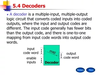
More on Decoders Recap: When enabled: the input combination value (i) is the subscript of the output that is asserted. Otherwise, the output is zero. Where i is i1 & i0 concatenated. When not enabled all outputs are zero. Making larger decoders: A decoder is used to select the appropriate output decoder y0 y1 y2 2x4 decoder G y3 i0 i1 Logic System Design I
Expanding Decoders 3x8 Decoder using only 2x4 decoders y0 y0 y0 y0 y0 y0 y1 y1 y1 y1 y1 y1 y2 y2 y2 y2 y2 3x8 decoder y2 2x4 decoder 2x4 decoder 2x4 decoder 2x4 decoder 2x4 decoder G G G G G y3 y3 y3 y3 y3 y3 G i0 i0 i0 i0 i0 i0 i1 i1 i1 i1 i1 i1 ??? i2 y4 y5 y6 y7 Logic System Design I
3x8 Decoder • Connect the outputs as shown y0 y0 y0 • Connect the least significant inputs to the inputs of the output decoders y0 y4 y1 y1 y1 y1 y5 y2 y2 y2 2x4 decoder 2x4 decoder 2x4 decoder y2 y6 • Each combination of i1 & i0 will produce two asserted outputs; thus, we need to enable the decoder with the desired output and disable the others … G G G y3 y7 y3 y3 y3 • Connect the first level decoder shown based on the remaining inputs. In this case, i2 of the new decoder. When i2 = 0, the top decoder is enabled. When i2 = 1 the bottom decoder is enabled. i0 i0 i0 i1 i1 i1 • Connect the enable for the new decoder to the enable of the first level mux. i0 i0 i1 i1 z0 i2 G z0 z1 z1 NOTE: Unused inputs must connect to something … unused outputs are left hanging. Logic System Design I
4x12 Decoder (non-std.) Decode binary word to 1-of-12 code (12 outputs) Logic System Design I
4-to-12 Decoder (non-std.) y0 y0 y0 y0 y0 y4 y8 y0 y1 y1 y1 y1 y1 y1 y9 y5 y2 y2 y2 y2 y2 2x4 decoder 2x4 decoder 2x4 decoder 2x4 decoder 2x4 decoder y10 y6 y2 G G G G G y3 y11 y7 y3 y3 y3 y3 y3 z0 i0 i0 i0 i0 i0 z0 i1 i1 i1 i1 i1 z1 z2 z1 Gint Vcc i0 i0 i0 i1 i1 i1 G0_L G1 i3 i2 z2 Gint Logic System Design I
4-to-16 Decoder 4x16 Decoder with an active-high enable y0 y0 y0 y0 y0 y4 y0 Y12 y8 y1 y1 y1 y1 y1 y9 y1 y5 y13 y2 y2 y2 y2 y2 2x4 decoder 2x4 decoder 2x4 decoder 2x4 decoder 2x4 decoder y6 y10 y2 y14 G G G G G y15 y7 y3 y11 y3 y3 y3 y3 y3 y12 y0 y4 y8 4x16 decoder y13 y1 y9 y5 i0 y10 y14 y2 y6 i1 z0 y11 y15 y7 y3 i2 i3 i0 i0 i0 i0 i0 i1 i1 i1 i1 i1 z0 z1 z1 z2 z3 G i0 i0 i0 i0 G i1 i1 i1 i1 i3 i2 z2 z3 Logic System Design I
Demultiplexer (demux) A demux performs the reverse operation from the mux The demux routes one input to 1-of-n outputs based on the select-line input combination System description for 4 output demux (2 select-lines) y0 = i·s1’·s0’ y1 = i·s1’·s0 y2 = i·s1·s0’ y3 = i·s1·s0 Recall from the decoder a description could be given as follows: y0 = G·s1’·s0’ y1 = G·s1’·s0 y2 = G·s1·s0’ y3 = G·s1·s0 Logic System Design I
Demux (concluded) You can see, from the previous expressions, that the demux could be implemented with a decoder that has an enable Just connect I to G of the decoder and you have a demux. Warning: Most CAD tools rely on the user knowing this fact … … the libraries do not contain any demuxes, just decoders. y0 y0 y0 y0 y0 y1 y1 y1 y1 y1 y2 y2 y2 y2 y2 2x4 decoder 2x4 decoder 2x4 decoder 2x4 decoder 2x4 decoder G G G G G y3 y3 y3 y3 y3 i0 i0 i0 i0 i0 i1 i1 i1 i1 i1 y0 y0 y0 y0 y0 s0 1 0 1 0 s1 y1 y1 y1 y1 y1 0 0 1 1 y2 y2 y2 y2 y2 y3 y3 y3 y3 y3 i i i i i Logic System Design I