Download
1 / 11
110 likes | 139 Views
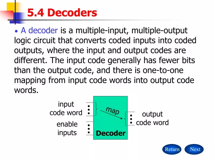
input code word. map. output code word. enable inputs. Decoder. Return. Next. 5.4 Decoders.

E N D
input code word map output code word enable inputs Decoder Return Next 5.4 Decoders • A decoder is a multiple-input, multiple-output logic circuit that converts coded inputs into coded outputs, where the input and output codes are different. The input code generally has fewer bits than the output code, and there is one-to-one mapping from input code words into output code words.
2-to-4 Decoder I0 Y0 I1 Y1 Y2 EN Y3 Return Back Next 5.4 Decoders • Binary decoder • The most common decoder circuit is an n-to-2ndecoder or binary decoder. Such a decoder has an n-bit binary input code and a 1-out-of-2n output code. Truth table for a 2-to-4 binary decoder ”don’t-care” notation
Return Back Next 5.4 Decoders Simulation
Return Back Next 5.4 Decoders • It is not necessary to use all of the outputs of a decoder, or even to decode all possible input combinations, e.g. a decimal or BCD decoder. • Logic Symbols for Lager-Scale Elements • The most basic rule is that logic symbols are drawn with inputs on the left and outputs on the right. The top and bottom edges of a logic symbol are not normally used for signal connections. However, explicit power and ground connections are sometimes shown at the top and bottom, especially if these connections are made on “nonstandard” pins.
1/2 74X139 G Y0 Y1 A Y2 B Y3 Return Back Next 5.4 Decoders • We use an inversion bubble to indicate an active-low pin and the absence of a bubble to indicate an active-high pin. • Active-high pins are given the same name as the internal signal, while active-low pins have the internal signal name with an overbar. external pin internal signal
74X139 Truth table for one-half of a 74x139 dual 2-to-4 decoder 1G 1Y0 1Y1 1A 1Y2 1B 1Y3 2G 2Y0 2Y1 2A 2Y2 2B 2Y3 1 4 Inputs Outputs 5 2 G B A Y3 Y2 Y1 Y0 6 7 1 X X 0 0 0 0 0 1 0 1 0 0 1 1 1 1 1 1 1 1 1 0 1 1 0 1 1 0 1 1 0 1 1 1 3 15 12 11 10 14 9 13 Return Back Next 5.4 Decoders • The 74x139 Dual 2-to-4 Decoder ( Logic diagram see P355 Figure 5-35 )
Inputs Outputs Y7 Y6 Y5 Y4 Y3 Y2 Y1 Y0 G1 G2A G2B C B A 1 1 1 1 1 1 1 1 1 1 1 1 1 1 1 1 1 1 1 1 1 1 1 1 1 1 1 1 1 1 1 0 1 1 1 1 1 1 0 1 1 1 1 1 1 0 1 1 1 1 1 1 0 1 1 1 1 1 1 0 1 1 1 1 1 1 0 1 1 1 1 1 1 0 1 1 1 1 1 1 0 1 1 1 1 1 1 1 0 X X X X X X 1 X X X X X X 1 X X X 1 0 0 0 0 0 1 0 0 0 0 1 1 0 0 0 1 0 1 0 0 0 1 1 1 0 0 1 0 0 1 0 0 1 0 1 1 0 0 1 1 0 1 0 0 1 1 1 Return Back Next 5.4 Decoders • The 74x138 3-to-8 Decoder ( Logic diagram see P358 Figure 5-37)
It has three enable inputs, G1, G2A, G2B , all of which must be asserted for the selected output to be asserted. • The equation for the external output signal Y5: Return Back Next 5.4 Decoders • The equation for the internal output signal Y5: Active-low
74X138 G1 Y0 G2A Y1 G2B Y2 Y3 Y4 A Y5 B Y6 C Y7 6 15 14 4 13 5 12 11 1 10 2 9 3 7 Return Back Next 5.4 Decoders • Traditional logic symbol of the 74x138
74X138 +5V R 15 6 G1 Y0 G2A Y1 G2B Y2 Y3 Y4 A Y5 B Y6 C Y7 DEC0 DEC1 DEC2 DEC3 DEC4 DEC5 DEC6 DEC7 4 14 5 13 12 U1 11 1 10 N0 N1 N2 N3 2 9 3 7 74X138 15 6 G1 Y0 G2A Y1 G2B Y2 Y3 Y4 A Y5 B Y6 C Y7 DEC8 DEC9 DEC10 DEC11 DEC12 DEC13 DEC14 DEC15 4 14 5 13 12 11 U2 1 10 2 9 3 7 Return Back Next 5.4 Decoders • Cascading Binary Decoders • The top decoder (U1) is enabled when N3 is 0, and the bottom one (U2) is enabled when N3 is 1.
a f b g e c d 74X49 11 a BI b c A d B e C f D g 3 10 9 5 8 1 6 2 13 4 12 Return Back 5.4 Decoders • Seven-Segment Decoders • Seven-segment display normally uses light-emitting diodes(LEDs) or liquid-crystal display(LCD) elements. • A seven-segment decoder has 4-bit BCD as its input code and the “seven-segment code” • Truth table for a 74x49 seven-segment decoder(See P374 table 5-21) • Logic diagram for a 74x49 seven-segment decoder(See P373 figure 5-45 )