Download
1 / 51
510 likes | 954 Views
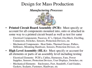
ME 330 Manufacturing Processes CUTTING PROCESSES. Overview of processes. Cutting processes. Principle of the process Process Process modeling Defects Design For Manufacturing (DFM) Process variation. Major cutting processes. For bulky object. Mechanical processes

E N D
Overview of processes Cutting processes
Principle of the process Process Process modeling Defects Design For Manufacturing (DFM) Process variation
Major cutting processes For bulky object • Mechanical processes • Machining and grinding. • Shearing, blanking, and punching (or sheet metalworking operations). • Water jet cutting (WJC or hydro-jet). • Abrasive water jet cutting (AWJC or abrasive hydro-jet). • Ultrasonic machining (USM) For sheet and plate For both sheet/plate and bulky object but brittle
Definition of sheets and plates Sheets: thickness is 1/64” (0.04 mm) to 1/4” (6 mm). Plates: thickness is greater than: 1/4” (6mm)
Principle of the manufacturing process Process Process modeling Defects Design For Manufacturing (DFM) Process variation
Principle of cutting sheets and plates: A shear stress is induced on the surface of the cross section area of plates or sheets. The shearing stress causes the fracture of two parts. The stress is induced by the force. Note that different physics are behind generation of shear stress. For instance, punch (solid) and die (solid) are combined to generate shear stress. Shear stress
Principle of the manufacturing process Structure/Configuration of the operation Process modeling Defects Design For Manufacturing (DFM) Process variation
Shearing, Blanking, and Punching Three principal configurations of systems that cut sheet metal: • Shearing • Blanking • Punching Different configurations of the manufacturing system or machine to generate shear stress, and they share the same principle of cutting. Remark: they are also called press working in manufacturing
Shearing Operation (a) Side view of the operation; (b) front view of the operation, equipped with an inclined upper cutting blade Ensure that the whole edge is touched by the punch
Blanking and Punching • Blanking (a) - sheet metal cutting to separate piece (called a blank) from surrounding stock • Punching (b) - similar to blanking except cut piece is scrap, called a slug
Equipment for Shearing, Blanking, and Punching • General configurations of manufacturing system: • punch, • die, • work piece • machine Tools & Tooling
Shearing material
Punch and Die in blanking and punching • Equipment of a punch and die for a punch operation • Equipment of a punch and die for a blanking operation Press machine Punch Die
Cons: Cost of tooling is a concern • The cost of tooling may even be higher than the press machine. • Punch and die may need frequently be changed due to wear, which is a part of the reasons for the high cost of tooling.
Summary of manufacturing science, technology, process/system Q1: Why are materials cut or removed? A1: Shear stress. Q2: How is shear stress created? A2: Solid mechanics (mechanical means). Q3: What is a configuration of work-piece and tool? A3: Shearing, blanking, and punching. Q4: How are work-piece and tool integrated into one further driven by a power? A4: Press machine or manufacturing system. Science Process/ Technology System
Non-traditional Cutting Processes Cutting force is not generated by solid state force such as solid punch and solid die.
Non-traditional Processes: why • Newly developed metals and non‑metals with special properties that make them difficult or impossible to cut or machine by the solid force approach. • Complex part geometries that cannot readily be accomplished by conventional cutting and machining. • Avoid surface damage that often accompanies with the conventional machining and cutting.
Principle of the manufacturing process Process Process modeling Defects Design For Manufacturing (DFM) Process variation
Major cutting processes • Mechanical processes • Machining and grinding. • Shearing, blanking, and punching (or sheet metalworking operations). • Water jet cutting (WJC or hydro-jet). • Abrasive water jet cutting (AWJC or abrasive hydro-jet). • Ultrasonic machining (USM)
Water Jet Cutting (WJC) or Hydro-jet Cutting • Uses high pressure, high velocity stream of water directed at work surface for cutting The punch is a water stream
WJC & Applications • Usually automated by CNC or industrial robots to manipulate nozzle along desired trajectory. • Water also acts as a cooling agent. • Can cut complex shaped parts. • Used to cut narrow slits in flat stock such as plastic, textiles, composites, floor tile, carpet, leather, and cardboard. • Not suitable for brittle materials (e.g., glass, especially tempered glass). The material is too hard, while the water-jet is relatively soft. The material tends to break and spread around, especially tempered glass.
Abrasive Water Jet Cutting (AWJC) • Abrasive particles are added to jet stream for quicker cutting, which increases the intensity of water jet so that the high force can be created. • Suitable to cut metals as well as common glasses. • Slower than laser cutting, but produces a cleaner finish. • Note that the water jet cut is tapered.
Major cutting processes • Thermal Energy Processes • Ram electric discharge machining (Ram EDM). • Wire electric discharge machining (Wire EDM). • Electron beam machining (EBM). • Laser beam machining (LBM). • Plasma arc cutting (PAC) or plasma arc machining (PAM). • Air carbon arc cutting. • OxyfuelCutting (OFC) or flame cutting.
Principle of the process Process Process modeling Defects Design For Manufacturing (DFM) Process variation
Electric Discharge Machining (EDM) Operating principle: Electric energy thermal energy remove the material To carry away the cut material
EDM Operation • One of the most widely used non-traditional processes. • Shape of the finished work surface produced by a shape of electrode tool. • Can be used only on electrically conducting work materials. • Requires dielectric fluid, which creates a path for each discharge as fluid becomes ionized in the gap. • Metal is melted/vaporized by the series of electrical discharges. • Can be very precise and produces a very good surface finish.
Work Materials in EDM • Work materials must be electrically conducting. • Hardness and strength of work material are not factors in EDM. • Material removal rate depends on melting point of work material.
Principle of the process Process Process modeling Defects Design For Manufacturing (DFM) Process variation
Wire EDM • Special form of EDM uses small diameter wire as electrode to cut a narrow kerf in work.
Operation of Wire EDM • Work is fed slowly past wire along a desired cutting path. • CNC is used for motion control. • While cutting, wire is continuously advanced between supply spool and take‑up spool to maintain a constant diameter. • Dielectric fluid is required. • Applied using nozzles directed at tool‑work interface or submerging work part.
Wire EDM Applications • Ideal for stamping die components. • Since kerf is so narrow, it is often possible to fabricate punch and die in a single cut. • Other tools and parts with intricate outline shapes, such as lathe form tools, extrusion dies, and flat templates.
Dental part cut from nitinolmaterialby wire EDM https://youtu.be/pBueWfzb7P0 https://youtu.be/RQmVplQ5bdE
Laser Beam Machining (LBM) • Uses the light energy from a laser to remove material by vaporization and ablation The punch is a light beam
LBM Applications • Drilling, slitting, slotting, scribing, and marking operations. • Drilling small diameter holes ‑ down to 0.025 mm (0.001 in). • Generally used on thin stock. • Work materials: metals with high hardness and strength, soft metals, ceramics, glass and glass epoxy, plastics, rubber, cloth, and wood.
Plasma Arc Cutting (PAC) • Uses plasma stream operating at very high temperatures to cut metal by melting. The punch is a plasma arc
Operation of PAC • Plasma = a superheated, electrically ionized gas. • PAC temperatures: 10,000C to 14,000C (18,000F to 25,000F). • Plasma arc generated between electrode in torch and anode work piece. • The plasma flows through water‑cooled nozzle that constricts and directs stream to desired location.
Applications of PAC • Most applications of PAC involve cutting of flat metal sheets and plates. • Hole piercing and cutting along a defined path. • Comparable to laser cutting, but cuts are usually more coarse. • Can cut any electrically conductive metal. • Most frequently cut metals: carbon steel, stainless steel, aluminum.
Important feature: Water-Jet, Laser, Plasma • Need to start the cut away from the wanted cut to prevent a rough surface irregularity where the cut starts Wanted cut Starting cut
Quality (In terms of tolerances & surface finish Summary of Cutting Processes for Sheets and Plates in terms of Quality & Cost Wire EDM Machining Water Jet Laser Punching/ Blanking Plasma Cost
Comparison: sheet and plate cutting • Plasma • Laser • Water-jet
Comparison: sheet and plate cutting Main criteria for comparison: Material Cost Quality Productivity
Comparison: sheet and plate cutting • Cost: decided by the speed of cutting (the faster the speed is, the lower the cost).
Major cutting processes • All the above processes are a mechanical process (X energy mechanical or thermal energy) • Electrochemical process: • Electrochemical Machining (ECM)
Principle of the process Process Process modeling Defects Design For Manufacturing (DFM) Process variation
Electrochemical Machining (ECM) • Material removal by anodic (work) (+) dissolution using cathode(tool) (-) in close proximity to work(anode) (+), and the two are separated by a rapidly flowing electrolyte E - + (+) (-) Electrode = cathode
Electrochemical Machining (ECM) • Material removal by anodic dissolution, using cathode (tool) in close proximity to work but separated by a rapidly flowing electrolyte Electrode = cathode .
Electrochemical Machining (ECM) Processes • Electrical energy used in combination with chemical reactions to remove material • Reverse of electroplating • Work material must be a conductor • Process variations: • Electrochemical machining (ECM) • Electrochemical deburring (ECD) • Electrochemical grinding (ECG)
ECM Operation • Material is depleted from anode work-piece (positive pole) and transported to a cathode tool (negative pole) in an electrolyte bath • Electrolyte flows rapidly between two poles to carry off depleted material, so it does not plateonto tool • Electrode materials: Cu, brass, or stainless steel • Tool has inverse shape of part • Tool size and shape must allow for the gap
General benefits to manufacture parts by cutting from sheets and plates: • Fast to manufacture • Parts are low in cost • Helps drive costs for assembled products down • From low to high quantities • Simple to complex parts • Parts can later be formed (bent) to make more complex shapes