Download
1 / 34
410 likes | 498 Views
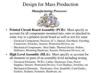
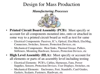
Manufacturing Processes. Introduction to Rapid Prototyping. Background. When developing a new product, there is always a need to see a single example or prototype. Idea is to catch any flaws or problems before a large investment is made in tooling and equipment.

E N D
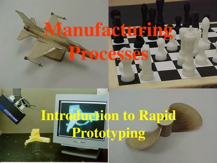
Manufacturing Processes Introduction to Rapid Prototyping
Background • When developing a new product, there is always a need to see a single example or prototype. • Idea is to catch any flaws or problems before a large investment is made in tooling and equipment. • Can also reduce development time:analyze and debug design early. • Need to be extremely competitive to beat competition to market.
History of Prototyping • Began with Artists/Craftspeople creating hand-made models. • Next was the evolution of CAD software. • This lead to CAD databases being used to generate CNC programs (subtractive processes). • Following subtractive processes was the development of additive processes ... generally called “Rapid Prototyping”.
Goals of Rapid Prototyping • Allows for the creation of models at greater speeds and with more precision. • Design process is improved as designers can experiment with variations of a product until the best results are obtained.
Goals of Rapid Prototyping • Rapid prototyping can: • Substantially reduce product development time, through rapid creation of 3D models. • Improve communication (visualization) within multidisciplinary design teams. • Address issues of increased flexibility & small batch sizes, while remaining competitive (rapid manufacture).
Advantages • Can produce physical model from CAD model in a matter of hours. • Great tool for visualization and concept verification. • Can use prototype in other manufacturing operations, such as casting and molding.
Basics • A geometric model is required which must include surface information. • Model is usually created in a solid modeling system such as Pro/Engineer, CATIA, I-DEAS etc. • 3D geometric models are mathematically sectioned into parallel cross-sections. • Each cross-section creates a 2D binding or curing tool path for model construction. • Models are constructed one layer at a time until complete. • Supports may also be required.
Stages • There are two stages to rapid prototyping: (1) Data preparation. (2) Model production.
Stages 1. Data preparation. • CAD data must be converted to .STL format. • It is characterized by triangular facets that are used to describe the shape of a closed 3D model. • Faceted surfaces must be completely bound. • Curved surfaces are approximated.
Stages • The .STL Format was developed by Albert Consulting Group. • Consists of x, y & z coordinates of triangles. • All adjacent triangles must share two vertices. • Translation software is either included in the CAD packages or via third party. • Resolution can be increased (# of triangles) • Trade-off: accuracy vs file size and processing time.
Stages 2. Model production: • There are major differences in materials used and build techniques within these technologies. • Here is a list of various RP technologies: • Stereolithography - 3D Systems • Selective Laser Sintering - DTM Corp • Laminated Object Manufacturing-Helisys • Three Dimensional Printing - Developed by MIT • Fused Deposition Modeling - Stratasys
RP Technologies • Stereolithography - 3D Systems
RP Technologies • Stereolithography Apparatus (SLA) - 3D Systems • Laser generated ultraviolet beam traces out cross-sections and solidifies the liquid polymer. • Component is built in vat of liquid resin. • Vat size limits prototype • SLA-250 (10 x 10 x 10”) US$210,000 • There are multiple materials currently available for the SLA. • All are acrylates or epoxies (non-reusable thermosets).
RP Technologies • Stereolithography Apparatus (SLA) - 3D Systems • Accuracy - ranges from 0.1% to 0.5% of overall dimension from small to large parts. • Currently the most accurate RP technology. • Curing stability and support structures remain challenges.
RP Technologies • Stereolithography Stages: • CAD Design • CAD Translator • STL Verification • Orient • Support • Prepare • Build • Post Process
RP Technologies • Selective Layer Sintering (DTM Corp.)
RP Technologies • Selective Laser Sintering - DTM Corp • Developed at U. of Texas at Austin • Utilizes powder, rather that liquid polymer. • Potential exists for different materials including polycarbonate, PVC, ABS, nylon, polyester, polyurethane and casting wax.
RP Technologies • Selective Laser Sintering - DTM Corp • Sinterstation 2000 (12” dia. x 15” dp) US$425,000. Builds .4 - 2” per hour. • Layers from .003 - .02” thick. Accuracy from .005 to .015” depending on size. • Components can be recycled by crushing and converting back to powder. • Research is going into materials such as powdered metals, ceramics and composites.
SLS CO2 Laser Laser Optics / Scanning Mirror Leveling Roller Powder Bed Build Chamber Powder Cartridge
SLS Process • 1. Start with an STL file of your 3-D CAD data. • 2. Enter the data into the Sinterstation system. • 3. Spread a layer of powdered material. • As the process begins, a precision roller mechanism automatically spreads a thin layer of powdered SLS material across the build platform.
SLS Process • 4. Sinter a cross-section of the CAD file. • Using data from the STL file, a CO2 laser selectively draws a cross section of the object on the layer of powder. • As the laser draws the cross section, it selectively "sinters" (heats and fuses) the powder creating a solid mass that represents one cross section of the part.
SLS Process • 5. Repeat. The system spreads and sinters layer after layer until the object is complete. • 6. Remove the part. Once the part is complete, remove it from the part build chamber and blow away any loose powder. • 7. Finish as desired. Use the part as is—or sand, anneal, coat, or paint it before using it for its intended application.
RP Technologies Laminated Object Manufacturing - Helisys
RP Technologies Laminated Object Manufacturing • Process uses bonded sheet material. Normally paper, but metals, plastics and composites are possible. • LOM-1015 (14” x 15” x 10”) US$95,000 • Sheets of .002 - .02” thick. • Accuracy of +/- 0.005” achievable. • Support provided by remainder of sheet.
RP Technologies Laminated Object Manufacturing • Manufacturing prototypes less fragile than polymers. • No internal stresses or curing shrinkage. • Paper waste is non-hazardous. • Need ventilation for smoke generated by paper burns. • Cannot build hollow cavities as single part.
RP Technologies • 3 Dimensional Printing - Z Corp.
RP Technologies Three Dimensional Printing - Z Corp.-Utilizes powdered material (starch/cellulose), spread out one layer at a time. - Adhesive is applied in droplets through a device similar to an inkjet printer head. - Internal supports not required. - May require post processing, depending on material and binder. - Work continues on limiting impact of binder drops, reducing jagged “print” edges and flow control for the binder.
RP Technologies Build Process - 3DP • 1. The machine spreads a layer of powder from the feed box to cover the surface of the build piston. • 2. System then prints binder solution onto the loose powder, forming the first cross-section. Where the binder is printed, the powder is glued together. The remaining powder remains loose and supports the layers that will be printed above.
RP Technologies Build Process - 3DP • 3. When the cross-section is complete, the build piston is lowered slightly, a new layer of powder is spread over its surface, and the process is repeated. • 4. The part grows layer by layer in the build piston until the part is complete, completely surrounded and covered by loose powder. • 5. Finally the build piston is raised and the loose powder is vacuumed away, revealing the complete part.
RP Technologies Fused Deposition Modeling - Stratasys
RP Technologies Fused Deposition Modeling • Stratasys uses .050” dia. thermoplastic filament • Gantry type robot moves extruder head in two principal directions over a platform. • Thermoplastic is extruded through a small orifice in extruder head at 270 degrees F. • As head moves, material is deposited over foam foundation. • Supports are made of a different type of plastic. Can be easily removed by hand. • Low cost, easy to operate system.
RP Technologies Fused Deposition Modeling (FDM) Stages • CAD Design • CAD Translator • STL Verification • Orient • Slice Model • Create Supports • Create Roads • Build Model • Post Process
Areas of R&D dealing with Part Accuracy Improvement • Mathematical area: • potential use of CSG and ray tracing vs .STL • improving facet approximations • Process related area: • increasing z step resolution • developing layer registration • Material related area: • material selection/development • considerations of stress relief, alternate build techniques to reduce deformation
Examples of RP in Research • Molecular Modeling • Protein Kinase • Earth Science • Fault modeling • Terrain surfaces • Mechanical • Specific component models • Clearance, fit, function verification • Design process development • Medical • Creation of mold blanks • Customized devices for specific patients • Mathematical Surface Visualization