Download
1 / 67
690 likes | 943 Views
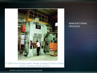
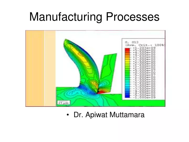
Manufacturing Processes. Dr. Apiwat Muttamara. Metal Cutting. 1.Traditional Machine Turning Milling etc. 2. Non-traditional Machine Laser, EDM etc. Chip. Turning. Propose . The operational uses and parameters, T he general layout of controls, accessories, associated tooling

E N D
Manufacturing Processes • Dr. Apiwat Muttamara
Metal Cutting 1.Traditional Machine • Turning • Milling etc. 2. Non-traditional Machine • Laser, EDM etc. Chip
Propose • The operational uses and parameters, • The general layout of controls, accessories, associated tooling • It takes a considerable time to become a skilled lathe operator and to possess all the skill of hand that goes with it. Therefore it is not expected that you will be manually skilled on completion of the module but you will have gained intellectually, by practical involvement, some skill of hand will be achieved.
apron Centre Lathe
Bed - the main frame,H-beam on 2 V-support • It has guideways for carriage to slide easilylengthwise Headstock • The spindle is driven through the gearbox Tailstock - Quill- Lath center, Tooling reference • Drill
A Plain Lath Center Quill Tailstock Chuck
Figure 2c. Taper Turning • Figure 2e. Radius Turning Attachment
CHUCK JAW Bevel pinion Bevel gear with spiral scroll
Face Plate Counterweght Workpiece
Face plate Dog Workpiece Lathe Center
Steady rest Three Adjustable Jaws
Basic Metal Cutting Theory RAKE Relief
Rake Angle • The larger the rake angle, the smaller the cutting force on the tool, • A large rake angle will improve cutting action, but would lead to early tool failure • A compromise must therefore be made between adequate strength and good cutting action. • Clearance Angle • Clearance should be kept to a minimum, as excessive clearance angle will not improve cutting efficiency and will merely weaken the tool.
Characteristics of Tool Material • Hot Hardness • the ability to retain its hardness at high temperatures. • Strength and Resistance to Shock • At the start of a cut the first bite of the tool into the work results in considerable shock • Low Coefficient of Friction
Tool Materials in Common Use • High Carbon Steel • Contains 1 - 1.4% carbon with some addition of chromium and tungsten to improve wear resistance. • The steel begins to lose its hardness at about 250° C, and is not favoured for modern machining operations where high speeds and heavy cuts are usually employed. • High Speed Steel (H.S.S.) • Steel, which has a hot hardness value of about 600° C, • commonly used for single point and multi point cutting tools • Cemented Carbides (WC-Co) • An extremely hard material made from tungsten powder. • Carbide tools are usually used in the form of brazed or clamped tips • HSS may be readily machined using carbide tipped tool. • High cutting speeds may be used and materials difficult to cut with HSS
TiC or TiN or TiCN, Al2O3 WC-Co Coating Materials for Cutting tool PCD Polycrystalline Diamond CBN Cubic Boron Nitride
CERMET Ceramic+metal
Chip Formation & Chip Breaker material & cutting conditions These conditions include the type of tool used tool, rate of cutting condition of the machine and the use or absence of a cutting fluid.
Continuous Chip - The chip leaves toolsa long ribbon -common when cutting most ductile materials such as mild steel, copper and Aluminium. Ideal Chip It is associated with good tool angles, correct speeds and feeds, and the use of cutting fluid.
Discontinuous Chip -resulted from cutting brittle metals such as cast iron and cast brass with tools having small rake angles. There is nothing wrong with this type of chip in these circumstances
Continuous Chip with Builtup Edge(BUE) This is a chip to be avoided and is caused by small particles from the workpiece becoming welded to the tool face under high pressure and heat. The phenomenon results in a poor finish and damage to the tool. It can be minimised or prevented by using light cuts at higher speeds with an appropriate cutting lubricant
Cutting Speed • Where: N = Spindle Speed (RPM)CS = Cutting Speed of Metal (m/min)d = Diameter of Workpiece
Feed • The term `feed' is used to describe the distance the tool moves per revolution of the workpiece and depends largely on the surface finish required. For roughing out a soft material a feed of up to0.25 mm per revolution may be used. With tougher materials this should be reduced to a maximum of 0.10 mm/rev. Finishing requires a finer feed then what is recommended.
Types of Milling Machine • Horizontal Vertical
Slab MillsFor heavy cutting of large and flat surfaces Side and Face Cutters Slitting Saw
End mill • Cutting tools for Vertical Millinga. End Mills Rough Cut End MillsFor rapid metal removal. • End Mill
Slot Drill Face Milling Cutters
INSERTENDMILL • INSERTENDMILL
Insert Seat
Spindle Speed • Spindle speed in (R.P.M.) where -- N = R.P.M. of the cutterCS = Linear Cutting Speed of the material in m/min. ( see table 1 ) d = Diameter of cutter in mm
Feed Rate • Feed rate (F) is defined as the rate of travel of the workpiece in mm/min. • F = f . u . N • where -- F = table feed in mm/min f = movement per tooth of cutter in mm ( see table 1 ) u = number of teeth of cutter N = R.P.M. of the cutter
F = f . u . N Table 1
Depth of Cut • Depth of cut is directly related to the efficiency of the cutting process. • For a certain type of cutter, a typical range of cut will be recommended by the supplier.
Feed Direction Up Cut Down Cut,Climb Milling • direction opposite to the table. • conventional milling • Backlash • CNC milling machine. • Require less power in feeding the table • Give a better surface finish on the workpiece.
T-Slot Forming cutting tool
Gear Cutting INDEXING HEAD