Download
1 / 25
260 likes | 471 Views
Electron beam diagnostic methods. William S. Graves MIT-Bates Laboratory. Presented at 2003 ICFA S2E Workshop DESY-Zeuthen August, 2003. Experimental Methods. Hardware/software controls. Thermal emittance measurement using solenoid scan.

E N D
Electron beam diagnostic methods William S. Graves MIT-Bates Laboratory Presented at 2003 ICFA S2E Workshop DESY-Zeuthen August, 2003
Experimental Methods • Hardware/software controls. • Thermal emittance measurement using solenoid scan. • Cross-correlation of UV photoinjector drive laser with 100 fs IR oscillator. • Streak camera time resolution • Electron beam longitudinal distribution measured using RF zero phasing method. • Slice transverse parameters are measured by combining RF zero phase with quadrupole scan. • Will not address undulator diagnostics. See Shaftan, Loos, Doyuran. Enables injector optimization and code benchmarking.
DUVFEL Facility at BNL 50 m Coherent IR diagnostics 1.6 cell gun with copper cathode NISUS 10m undulator Bunch compressor with post accel. 70 MeV Bend Undulators Bend Linac tanks 5 MeV 70-200 MeV Triplet Triplet RF zero phase screen Dump Dump 30 mJ, 100 fs Ti:Sapphire laser Photoinjector: 1.6 cell BNL/SLAC/UCLA with copper cathode 4 SLAC s-band 3 m linac sections Bunch compressor between L2 and L3 Approximately 60 CCD cameras on YAG screens.
Control system Automated measurements very important for gathering large amounts of data and repeating studies. All sophisticated control is done in the MATLAB environment on a PC. Physicists quickly integrate hardware control with data analysis. Low level control is EPICS on a SUN and VME crates.
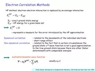
(1) (2) (3) Thermal Emittance
0.74 0.68 0.72 0.67 0.7 0.66 0.68 0.65 Emittance (mm-mrad) 0.66 Emittance (mm-mrad) 0.64 0.64 0.62 0.63 Charge 2 pC Energy 3.7 MeV Laser spot 0.5 mm RMS 0.6 0.62 FWHM 3 ps Energy 3.7 MeV Laser spot 0.5 mm RMS 0.58 0.61 0 2 4 6 8 10 0 5 10 15 20 FWHM (ps) Charge (pC) Projected emittance vs charge and FWHM HOMDYN simulations estimate limits on maximum bunch length and charge. Choose working parameters of 2 pC, 2 ps FWHM. Simulation Simulation YAG:Ce screen very useful for low charge, high resolution profiles. Screen thickness, surface quality, multiple reflections, and camera lens depth-of-focus and resolution are all important issues.
Can measure • charge • energy • x and y centroid • x and y beamsize • px and py 1cm Solenoid Scan Layout 65 cm 33 cm 12 cm YAG screen Mirror Dipole trim Telecentric lens magnif. = 1 1.6 cell photoinjector Solenoid CCD Camera • YAG:Ce screen very useful for low charge, high resolution profiles. • Screen thickness, surface quality, multiple reflections, and camera lens depth-of-focus and resolution are all important issues. See SLAC GTF data.
pop02a.bmp -9 File: a10pc.txt x 10 a = -30.8 ± 1.7 8 b = 8.11 ± 0.44 m e = 0.605 ± 0.025 mm-mrad 5 7 N s = 0.773 ± 0.0177 mm s ' = 2.94 ± 0.0658 mrad 6 10 E = 3.69 MeV 5 15 11 4 s 20 3 2 25 1 30 0 5 10 15 20 25 30 102 103 104 105 106 107 108 Solenoid Current (Amp) Hor. RMS width = 39.5 um 2000 1500 Intensity (A.U.) 1000 500 0 0 50 100 150 200 250 300 Beam size (um) Low Energy Beam Measurements pixels • Video processing • 3x3 median filter applied. • Dark current image subtracted. • Pixels < few % of peak are zeroed. Error estimates Monte Carlo method using measured beam size jitter.
Horizontal Vertical 1.2 1.2 1 1 0.8 0.8 (mm-mrad) (mm-mrad) 0.6 0.6 N N e e 0.4 0.4 0.2 0.2 0 0 0 0.2 0.4 0.6 0.8 1 1.2 0 0.2 0.4 0.6 0.8 1 1.2 Horizontal RMS laser size (mm) Horizontal RMS laser size (mm) Emittance vs laser size Emittance shows expected linear dependence on spot size. Small asymmetry is always present. FWHM 2.6 ps Charge 2.0 pC Gradient 85 MV/m RF phase 30 degrees
9 1.6 8 1.4 7 1.2 6 1 5 RMS ebeam hor. divergence (mrad) RMS e-beam hor. size (mm) 0.8 4 0.6 3 0.4 2 0.2 1 0 0 0 0.2 0.4 0.6 0.8 1 1.2 0 0.2 0.4 0.6 0.8 1 1.2 RMS laser hor. size (mm) RMS laser hor. size (mm) Beam size and divergence vs laser spot size High Size Divergence High Low Low Error bars are measured data. Blue lines are from HOMDYN simulation using RF fields from SUPERFISH model and measured solenoid B-field. Upper blue line has 1/2 cell field 10% higher than full cell. Lower blue line has 1/2 cell field 10% lower than full cell.
Emittance vs RF phase Error bars are measured data points. Curve is nonlinear least squares fit with βrf and Φcu as parameters: βrf = 3.10 +/- 0.49 and Φcu = 4.73 +/- 0.04 eV. The fit provides a second estimate of the electron kinetic energy Ek = 0.40 eV, in close agreement with the estimate from the radial dependence of emittance.
Time profile of UV laser pulse 2 Signal (V) 1.5 1 0.5 0 40 30 Phase matching angle (mrad) 20 100 fs IR 10 200 fs blue 0 -10 2 0 -20 -2 Power meter -4 Time (ps) -30 -6 5 ps UV -8 -40 -10 BBO crystal Cross-correlaton difference frequency generation – experiment by B. Sheehy and H. Loos Phase matching angle of harmonic generation crystals used to produce UV affects time and spatial modulations. Note: “Sub-ps” streak camera is inadequate for this measurement
Laser masking of cathode image Above: Laser cathode image with mask removed showing smooth profile. Below: Resulting electron beam showing hot spot of emission. Above: Laser cathode image of air force mask in laser room. Below: Resulting electron beam at pop 2.
50 100 150 200 250 300 350 400 450 500 Time 100 200 300 400 500 Streak Camera • Hammamatsu FESCA 500 • 765 fs FWHM measured resolution • Reflective input optics (200-1600 nm) • Wide response cathode (200-900 nm) • Optical trigger (<500 fs jitter) • Designed for synchroscan use. Also good single-shot resolution. • 6 time ranges: 50 ps - 6 ns 50 ps window Streak image Very helpful for commissioning activies and for timing several optical signals. Limited time resolution below 1 ps.
234 220 232 230 215 228 226 210 224 222 205 220 218 signal (arb units) signal (arb units) 216 200 214 212 195 210 208 190 206 204 185 202 200 180 198 196 6 8 10 32 34 36 38 streak delay (picoseconds) streak delay (picoseconds) Streak camera time profiles of laser pulses 360 340 320 300 280 signal (arb units) 260 240 220 200 180 160 14 16 18 20 22 24 26 streak delay (picoseconds) Amplified IR 796 nm FWHM 1.01 ps single shot UV 266 nm FWHM 2.40 ps singleshot Oscillator 796 nm FWHM 765 fs Time resolution depends on photon energy: energetic UV photons create photoelectrons with energy spread that degrades time resolution
RF zero-phase time profile L2 phase varies, amp. fixed L4 phase = +/-90, amp. set to add known chirp L3 phase = +90, amp. set to remove chirp L1 phase = 0, amp. fixed Chicane varies from 0 cm < R56 < 10.5 cm L4 L3 L2 L1 Pop 14 YAG screen YAG images at pop 14 L3 corrects residual chirp, L4 is off L4 phase = -90 degrees L4 phase = +90 degrees
Quad scan during RF zero phase Movie of slice emittance measurement.
Left side Beam size squared vs quadrupole strength. Each plot is a different time slice of beam. Right side Circle is matched, normalized phase space area at upstream location. Ellipse is phase space area of slice at same location. Straight lines are error bars of data points projected to same location. Collaboration with Dowell, Emma, Limborg, Piot Software is used to time-slice beam.
Slice emittance and Twiss parameters z is parameter that characterizes mismatch between target and each slice. z = ½ (b0g – 2 a0a + bg0) a0, b0, g0 are target Twiss param. a, b, g are slice Twiss param. Beam Parameters: 200 pC, 75 MeV, 400 fs slice width Note strongly divergent beam due to solenoid overfocusing at tail, where current is low. Space charge forces near cathode caused very different betatron phase advances for different parts of beam.
Different slices require different solenoid strength Current projection Tail Time Head Tail Head Tail Head Tail Head Tail Head Tail Head Vertical dynamics Lattice is set to image end of Tank 2 to RF-zero phasing YAG. Particles in tail of beam are diverging, and in head converging. Head has higher current and so reaches waist at higher solenoid setting. Increasing solenoid current
Solenoid Eyn Alpha Beta 98 A 3.7 um (3.2) 0.4 (1.0) 1.3 m (1.3) 104 A 2.1 um (2.8) -6.9 (-3.6) 9.8 m (6.8) 108 A 2.7 um (2.7) -9.0 (-9.6) 45 m (36) Solenoid = 98 A Slice emittance vs solenoid strength. Charge = 200 pC. Data Parmela Projected Values (parmela in parentheses) Solenoid = 108 A Solenoid = 104 A
Slice parameters vs charge 10 pC 50 pC Low charge cases show low slice emittance and little phase space twist. 200 pC 100 pC High charge cases demonstrate both slice emittance growth and phase space distortion.
50 100 150 50 100 150 200 250 300 File: csr01, FWHM = 2.2 ps 200 150 Current (A) 100 50 0 0 2 4 6 Time (ps) Longitudinal structure Analysis of RF zero phasing data can be complicated by modulations in energy plane. See contribution from T. Shaftan for detailed description.
RF zero phasing vs RF deflectors • RF zero phasing • Method uses accelerating mode to “streak” the beam by increasing the energy spread (chirping). • Uncorrelated energy spread is ~5 keV and coherent modulations can be ~20 keV. Streak chirp must be much larger than this. • Time and energy axes are difficult to disentangle. • RF deflector cavity • Transverse momentum is ~ 1 eV/c. Relatively small deflecting field gives excellent time resolution. • Less sensitive to coherent energy modulations. • Can obtain simultaneous time/energy/transverse beam properties when combined with dipole in other plane.
Concluding Remarks • Experience seems to indicate that most differences between experiment and simulation are due to experimental inaccuracies. • Beam can be used to diagnose many hardware/applied field difficulties. • “Easy to use” control system integrating realtime analysis and hardware/beam control very important. • With adequate diagnostics, meeting beam quality and FEL performance goals is straightforward. • See work by Shaftan, Loos, Doyuran of BNL on undulator diagnostics and trajectory analysis.