Download
1 / 12
120 likes | 255 Views
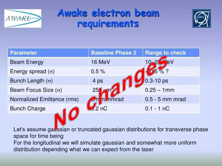
Awake electron beam requirements. No changes. Let’s assume gaussian or truncated gaussian distributions for transverse phase space for time being For the longitudinal we will simulate gaussian and somewhat more uniform distribution depending what we can expect from the laser.

E N D
Awake electron beamrequirements No changes Let’s assume gaussian or truncated gaussian distributions for transverse phase space for time being For the longitudinal we will simulate gaussian and somewhat more uniform distribution depending what we can expect from the laser
Laser requirements 500 mJ 50 mJ
Laser update • We still assume using copper cathodes • Prefer a solution where Amplitude delivers a UV laser beamThis means they take care of the compression and the 3rd harmonic generation. • CERN would then transport the UV to the gun and cathode. • UV pulse required:Wavelength: 262 nm; 500 uJpulse energy and a FWHM pulse length of 10 ps.This pulse would guarantee the base line parameters and the 1 nC option. • For the short pulse 0.3 ps we would need only 50 uJ in the UV assuming that we would have to produce only 0.1 nC of charge (limited by ablation) • Pulse compression independent from the one for the proton beam Independent pulse picker allowing to use only some pulses out of the 10 Hz rep. rate. • The specification for an IR beam would be a pulse energy of 50 mJ. • We will still try to investigate the space constraints and keep the option to use different cathodes.
Electron source layout Laser table needs to be integrated as well
Electron source layout • Comments: • Layout is advancing • Some conflicts with the overall length • Need to optimise cathode accelerating structure distance • Need to specify quadrupoles • Study cathode loading system options • Study shielding design and layout
Electron source design Oznur Mete, Cockcroft
Starting points for calculations 727 98 Proton line: the top mirror in vacuum before the laser core tunnel Electron line: intersection of the “electron” laser beam with the vertical plane formed by 2 vacuum mirrors for “proton” beam Valentine and Mikhail
Proton line: path to plasma cell 7387+1188+320+19929 = 28824 mm 320 7387 1188 vertical 19929
Electron line: path to photocathode 9846+1087+1320+500+817 = 13570 mm 9846 500 817 1320 1087 vertical Optical table 1000x1800
Electron beam path from photocathode to plasma cell 4627+377*4+3683+736+1536+4319 = 16409 mm 4627 377 3683 377 377 736 377 1536 4319
Summary • A variable delay of 0 - 200 mm in the electron line is required • Proton line path to plasma cell = 28824 mm • Electron line: laser path + electron path = 29979 mm difference = - 1155 mm is to be compensated by delaying the “proton” pulse (could it exist in the main amplifier ?) Delays due to compressor, THG, UV stretcher, telescope, are not counted!