Download
1 / 14
140 likes | 267 Views
Beam Diagnostic Laboratory. C. Bohn, G. Blazey, P. Piot, N. Vinogradov, G. Betzel. Introduction for Beam Diagnostics Laboratory.

E N D
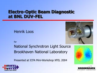
Beam Diagnostic Laboratory C. Bohn, G. Blazey, P. Piot, N. Vinogradov, G. Betzel
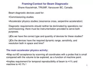
Introduction for Beam Diagnostics Laboratory • Main Mission: R&D on charged particle beam diagnostics for e+/e- linear colliders (ILC), other demanding e- accelerators (FELs and novel light source concepts) and proton drivers. • Hardware: A small e- accelerator for • in-house testing/troubleshooting of diagnostics before installing them in other accelerator beamlines (such as ILCTA at Fermilab or AWA at Argonne), • training students, and • doing fundamental beam physics experiments.
Phased Plans for Beam Diagnostics Laboratory • Ultimate Goal: Operate a low-average-current, multi-MeV (20-40 MeV is possible) racetrack-microtron accelerator to drive coherent light sources. • Phase 1:6 MeV thermionic rf gun • Phase 2:6 MeV photoemission rf gun [Phase 2 beam current will be reduced compared to Phase 1] • Phase 3:20 MeV racetrack microtron (but we will go as high as permissible per our radiation shielding capability)
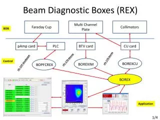
Basic Design of the electron beam line PS Electron gun Q BPM BCM Q 70 deg. bend BPM PS FC S S PS Adjustable slits Q BPM BPM – Beam Profile Monitor FC – Faraday cap Q Q PS BPM BCM Q – Magnetostatic quad FC PS – pumping station S – steering system 70 deg. bend BCM – beam current monitor
Expected parameters of electron beam Reminder: The eventual photoemission gun and racetrack microtron will operate with significantly less average beam current, i.e., ≤1 μA.
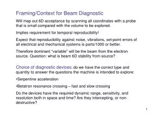
Shielding Estimates for Beam Diagnostics Laboratory • Requirement: External dose rates <1.0 mrem/hr per the administrative control levels set by DOE. • Tools & Methods: NCRP Report No. 51, MARS15 Sim. Pkg. • Assumptions: • Maximum energy & average current • Simplified geometry: removed electron gun, magnets, most of the beam pipe, maze entrance(s), supports, structural metal inside concrete walls • Uniform density of all materials • Initial and final energy of scattered electrons are equal (in NCRP calculation only)
BDL shielding estimates Model layout illustrating neutron scattering, with a cubic beam stop centered 1.25 m from barrier walls Pb Beam stop Electron gun Beamline Beam stop
BDL shielding estimates • MARS15 Simulations • Parameters (ref. from NCRP calc.): • 60 cm concrete walls, 20 cm lead beam stop, origin of impingement placed 1.25 m from wall • Results for 20 MeV, 0.06 μA beam: • Normal-operating scenario: 0.08 << 1.0 mrem/hr • Worst-case scenarios: • ~100% of radiation impinging fwd-directed barrier wall (w/ Pb beam stop only): 1.0 mrem/hr • Beam misalignment (w/ 10 cm Pb at 10 cm from beam pipe): 0.82 < 1.0 mrem/hr
BDL shielding estimates Absorbed Dose Rate (Gy/yr), 20 MeV & 0.06 A
BDL shielding estimates ~5·10-3 ~5·10-11 Absorbed Dose Rate (Gy/yr) Power density, neutrons (Gy/s) Both equate to approx. ~0.02 mrem/hr
BDL shielding estimates • Problem: MARS results are about an order of magnitude lower than those found by NCRP calculations. Why? • Methodology of NCRP guidelines are inherently conservative (this is a good thing) • NCRP data is inadequate to make a thorough analysis • MARS input code may be incorrect • Solution: • Reduce margin of error in calculations (updated NCRP reports, alternate sources?) • Verify MARS code
Floor Plan of the Beam Diagnostic Laboratory Accelerating hall surrounded by concrete shielding Assembly room with clean tent and related equipment Accelerator control room Office area Laser room
Accelerating Hall Concrete shielding covered with lead Beamline on two optical tables “Chicane” type entrance from service areas Sliding door
Conclusions • The conceptual design of the Beam Diagnostic Laboratory has been prepared • The basic requirements for the radiation shielding have been established • To start the actual engineering design of the concrete/lead vault the shielding specifications need to be checked by independent qualified experts