Download
1 / 32
770 likes | 1.71k Views
Electron Beam and Laser Beam Machining.

E N D
Electron Beam and Laser Beam Machining
Fig. shows the schematic representation of an electron beam gun, which is the heart of any electron beam machining facility. The basic functions of any electron beam gun are to generate free electrons at the cathode, accelerate them to a sufficiently high velocity and to focus them over a small spot size. Further, the beam needs to be maneuvered if required by the gun. The cathode is generally made of tungsten or tantalum. Such cathode filaments are heated, often inductively, to a temperature of around 25000C. Such heating leads to thermo-ionic emission of electrons, which is further enhanced by maintaining very low vacuum within the chamber of the electron beam gun. Moreover, this cathode cartridge is highly negatively biased so that the thermo-ionic electrons are strongly repelled away form the cathode. This cathode is often in the form of a cartridge so that it can be changed very quickly to reduce down time in case of failure.
Just after the cathode, there is an annular bias grid. A high negative bias is applied to this grid so that the electrons generated by this cathode do not diverge and approach the next element, the annular anode, in the form of a beam. The annular anode now attracts the electron beam and gradually gets accelerated. As they leave the anode section, the electrons may achieve a velocity as high as half the velocity of light. The nature of biasing just after the cathode controls the flow of electrons and the biased grid is used as a switch to operate the electron beam gun in pulsed mode. After the anode, the electron beam passes through a series of magnetic lenses and apertures. The magnetic lenses shape the beam and try to reduce the divergence. Apertures on the other hand allow only the convergent electrons to pass and capture the divergent low energy electrons from the fringes. This way, the aperture and the magnetic lenses improve the quality of the electron beam.
Then the electron beam passes through the final section of the electromagnetic lens and deflection coil. The electromagnetic lens focuses the electron beam to a desired spot. The deflection coil can manoeuvre the electron beam, though by small amount, to improve shape of the machined holes. Generally in between the electron beam gun and the work piece, which is also under vacuum, there would be a series of slotted rotating discs. Such discs allow the electron beam to pass and machine materials but helpfully prevent metal fumes and vapour generated during machining to reach the gun. Thus it is essential to synchronize the motion of the rotating disc and pulsing of the electron beam gun. Electron beam guns are also provided with illumination facility and a telescope for alignment of the beam with the work piece.
Workpiece is mounted on a CNC table so that holes of any shape can be machined using the CNC control One of the major requirements of EBM operation of electron beam gun is maintenance of desired vacuum. Level of vacuum within the gun is in the order of 10-4 to 10-6 Torr. Maintenance of suitable vacuum is essential so that electrons do not loose their energy and a significant life of the cathode cartridge is obtained. Such vacuum is achieved and maintained using a combination of rotary pump and diffusion pump. Diffusion pump is essentially an oil heater. As the oil is heated the oil vapour rushes upward where gradually converging structure as shown in Fig. is present. The nozzles change the direction of motion of the oil vapour and the oil vapour starts moving downward at a high velocity as jet. Such high velocity jets of oil vapour entrain any air molecules present within the gun. This oil is evacuated by a rotary pump via the backing line. The oil vapour condenses due to presence of cooling water jacket around the diffusion pump.
Electron beam gun provides high velocity electrons over a very small spot size. Electron Beam Machining is required to be carried out in vacuum. Otherwise the electrons would interact with the air molecules, thus they would loose their energy and cutting ability. Thus the workpiece to be machined is located under the electron beam and is kept under vacuum. The high-energy focused electron beam is made to impinge on the workpiece with a spot size of 10 – 100 μm. The kinetic energy of the high velocity electrons is converted to heat energy as the electrons strike the work material. Due to high power density instant melting and vaporisation starts and “melt – vaporisation” front gradually progresses, as shown in Fig. Finally the molten material, if any at the top of the front, is expelled from the cutting zone by the high vapour pressure at the lower part. Unlike in Electron Beam Welding, the gun in EBM is used in pulsed mode Localized heating by focused electron beam Gradual formation of hole Penetration till the auxiliary support Removal due to high vapour pressure
Electron Beam Process – Parameters • The accelerating voltage (100 KV) • The beam current (250 µA – 1A • Pulse duration (50 µS– 50 mS) • Energy per pulse (100 J/pulse) • Power per pulse • Lens current • Spot size (10 µm – 500 µm) • Power density Advantages and Limitations EBM provides very high drilling rates when small holes with large aspect ratio are to be drilled. Moreover it can machine almost any material irrespective of their mechanical properties. As it applies no mechanical cutting force, work holding and fixturing cost is very less. Further for the same reason fragile and brittle materials can also be processed. The heat affected zone in EBM is rather less due to shorter pulses. EBM can provide holes of any shape by combining beam deflection using electromagnetic coils and the CNC table with high accuracy. However, EBM has its own share of limitations. The primary limitations are the high capital cost of the equipment and necessary regular maintenance applicable for any equipment using vacuum system. Moreover in EBM there is significant amount of non-productive pump down period for attaining desired vacuum. However this can be reduced to some extent using vacuum load locks. Though heat affected zone is rather less in EBM but recast layer formation cannot be avoided.
Electron Beam Machine Four sub-systems Electron beam gun: Electrons are generated by thermionic emission from hot tungsten cathode. In E-beam gun for cutting & drilling applications, there is a grid between anode & cathode on which negative voltage is applied to pulse / modulate the e-beam. Rotating shutter Mode of E-beam Operation: For drilling and cutting-Pulsed electron beam Single pulse : A single hole in thin sheet; Multiple pulses: To drill in a thicker material. For welding : DC electron beam Parameters so chosen that loss of material due to vaporization is minimum. Power supply: Up to 150kV, Current : 1.5A. Vacuum-chamber: 10-4-10-6 Torr achieved by rotary pump backed diffusion pump. Vacuum compatible CNC workstation
* Energy of Electrons Electrons and latticeof material through collisions. * Energy transfer Function of electron energy. e-energy, Transfer rate * Maximum rise in temperature- At a certain depth, not at the surface, unlike laser heating.* Due to scattering of electrons, its energy not localized within the area determined by the diameter of beam – Poor material removal efficiency • Depth of penetration: • = 2.6x10⁻¹⁷(V2 /) mm V=Accelerating Voltage (Volts) • = Material density (kg/mm3) Kinetic Energy of Electron= ½ me.v2 = e.V v (km/s) = 600V1/2 me=9.1x10⁻³¹kg, e=1.6x10⁻¹⁹Coulomb. KE is dissipated in the impinging material. Typical range: V=50kV, = 8g/cm3 8m Electron Velocity=10-50% of Light velocity
Process Capabilities : EBM: * A wide range of materials, such as stainless steel, nickel and cobalt alloys, copper, aluminum, titanium, ceramic, leather and plastic. * Cutting up to a thickness of 10mm : material removal by vaporization * Hole-diameter ranging from 0.1- 1.4mm in thickness up to 10mm. * High aspect (depth to diameter) 15:1 * Holes at very shallow angle from 200-900 * No much force to the work-piece, thereby allowing brittle and fragile materials to be processed without danger of fracturing. * Hole diameter accuracy + 0.02mm in thin sheets EBW (welding): * Deep penetration welding up 300mm in high vacuum * Various weld geometry: Butt, Lap, T- joints * Owing to very high power density a wide range of metals can be welded: steel, copper, nickel based alloys, aluminum alloys and refractory such as zirconium, tantalum, titanium and niobium.
Current Control: Hot cathode emits electrons and the thermionic emission is given by the Richardson- Dushman equation: j = A T2 exp(-eW/kT) Where j = Current density (amp/cm2) from the cathode surface W = Work function of the cathode material (Volts) T = Absolute Temperature of cathode (K) e = Electron charge (Coulomb) k = Boltzmann constant (1.3x10⁻²³J/K) A = Constant (~120Amp/cm2.K2) Temperature T - j Electrons emitted from cathode are in thermal equilibrium at temperature T and their velocity is govern by Maxwellian distribution. This is reflected in focusing the electrons on the work-piece. Cathode Material: Tungsten or thoriated tungsten
Application Examples: EB Drilling: Suitable where large no. of holes is to be drilled where drilling holes with conventional process is difficult due to material hardness or hole-geometry. Used in aerospace, instrumentation, food , chemical & textile industries. Thousands of tiny holes (0.1- 0.9+0.05mm) in Turbine (steel) engine combustor. Cobalt alloy fiber spinning heads. Filters & Screens used in food processing. Perforation in artificial leather to make shoes for air-breathing: 0.12mm hole made at 5000/s. EBW: Welding with minimum distortion- Finished components Parts of target pistols, Bimetal strips, Dissimilar metals, Aircraft gas turbine components, Automobile catalytic converter, etc.
Advantages of EBM: • Drilling & Cutting • Any material can be machined • No cutting forces are involved so no stresses imposed on part • Exceptional drilling speeds possible with high position accuracy and form • Extremely small kerf width, little wastage of material • Little mechanical or thermal distortion • Computer-controlled parameters • High aspect ratio • High accuracy • EBW (welding) • Minimum thermal input • Minimum HAZ & Shrinkage • High aspect ratio & Deep penetration • High purity, no contamination • Welds high-conductivity materials
Disadvantages of EBM : • High capital cost • Nonproductive pump down time • Recast at the edges • High level of operator skill required • Maximum thickness that can be cut about 10mm (3/8”) • A suitable backing material must be used • Ferrous material to be demagnetized as otherwise could affect the e-beam • Work area must be under a vacuum • High joint preparation & tooling costs for welding • X-ray shielding required • Seam tracking sometimes difficult.
Summary of EBM Characteristics: Mechanics of material removal : Melting, Vaporization Medium : Vacuum ( 10-4-10-6 Torr), Air with high power, high Voltage beam (not yet commercially popular) Tool : High velocity electron beam Maximum material removal rate : ~50mm3/min Specific cutting energy : ~1500J/mm3 Critical Parameters : Accelerating voltage, beam current, beam diameter, work speed, melting temperature Material applications : All materials Shape applications : Drilling fine holes, contour cutting, cutting narrow slots Limitations : High specific energy, Necessity of vacuum, Very high machine cost.
Quiz Questions 1. Mechanism of material removal in Electron Beam Machining is due to a) Mechanical erosion due to impact of high of energy electrons b) Chemical etching by the high energy electron c) Sputtering due to high energy electrons d) Melting and vaporization due to thermal effect of impingement of high energy electron Answer – (d) 2. Generally Electron Beam Gun is operated at a) Atmospheric pressure At 1.2 bar pressure above atmosphere c) At 10 – 100 mTorr pressure d) At 0.01 – 0.001 mTorr pressure Answer – (d)
Numerical Problems: • Estimate the penetration depth of electron beam accelerated at 100kV impinging in steel having density of 7.6g/cc. • = 2.6x10⁻¹⁷(V2 /) mm, V in Volts & in kg/mm3 • = 0.034m • 2. Electron Beam power required is proportional to material removal rate: P =C.Q • Where C is constant of proportionality & Q is MRR in mm3 /min. • Typical energy requirements for cutting are, • C = P/Q 12 W/mm3/min = 1000W / ( 250x10-3x0.5xV in mm/min) • V in mm/min = 1000/(12 x 0.25x0.5) = 667mm/min =11mm/s Determine the cutting speed to cut a 250 micron wide slot in a 0.5mm thick tungsten sheet using a 1kW electron beam
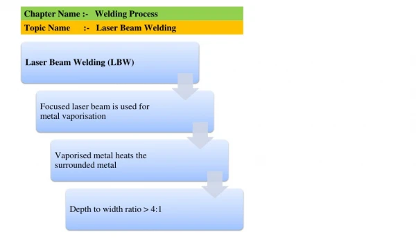
Laser Beam Machining Laser Beam Machining or more broadly laser material processing deals with machining and material processing like heat treatment, alloying, cladding, sheet metal bending etc. Such processing is carried out utilizing the energy of coherent photons or laser beam, which is mostly converted into thermal energy upon interaction with most of the materials. Nowadays, laser is also finding application in regenerative machining or rapid prototyping as in processes like stereo-lithography, selective laser sintering etc. Laser : Light Amplification by Stimulated Emission of Radiation Laser beam can very easily be focused using optical lenses as their wavelength ranges from half micron to around 70 microns. Focused laser beam as indicated earlier can have power density in excess of 1 MW/mm2. As laser interacts with the material, the energy of the photon is absorbed by the work material leading to rapid substantial rise in local temperature. This in turn results in melting and vaporization of the work material and finally material removal.
Lasing Medium • Many materials can be used as the heart of the laser. Depending on the lasing medium lasers are classified as solid state and gas laser. • Solid-state lasers are commonly of the following type • • Ruby which is a chromium – alumina alloy having a wavelength of 0.7 μm • • Nd-glass lasers having a wavelength of 1.64 μm • • Nd-YAG laser having a wavelength of 1.06 μm • These solid-state lasers are generally used in material processing. • The generally used gas lasers are • • Helium – Neon • • Argon • • CO2etc. – Wave length 10.6 µm • Lasers can be operated in continuous mode or pulsed mode. Typically CO2gas laser is operated in continuous mode and Nd – YAG laser is operated in pulsed mode.
Application • Laser can be used in wide range of manufacturing applications • • Material removal – drilling, cutting and tre-panning • Cladding • • Alloying • Welding • Drilling micro-sized holes using laser in difficult – to – machine materials is the most dominant application in industry. In laser drilling the laser beam is focused over the desired spot size. For thin sheets pulse laser can be used. For thicker ones continuous laser may be used. Advantages • In laser machining there is no physical tool. Thus no machining force or wear of the tool takes place. • Large aspect ratio in laser drilling can be achieved along with acceptable accuracy or dimension, form or location • Micro-holes can be drilled in difficult – to – machine materials • Though laser processing is a thermal processing but heat affected zone specially in pulse laser processing is not very significant due to shorter pulse duration. Limitations • High initial capital cost • High maintenance cost • Not very efficient process • Presence of Heat Affected Zone – specially in gas assist CO2 laser cutting • Thermal process – not suitable for heat sensitive materials like aluminium glass fibre laminate
QUIZ 1. Mechanism of material removal in Electron Beam Machining is due to a) Mechanical erosion due to impact of high of energy electrons b) Chemical etching by the high energy electron c) Sputtering due to high energy electrons d) Melting and vaporisation due to thermal effect of impingement of high energy electron 2. Mechanism of material removal in Laser Beam Machining is due to a) Mechanical erosion due to impact of high of energy photons b) Electro-chemical etching c) Melting and vaporisation due to thermal effect of impingement of high energy laser beam d) Fatigue failure 4. Laser Beam is produced due to a) Spontaneous emission b) Stimulated emission followed by spontaneous emission c) Spontaneous emission followed by Spontaneous absorption d) Spontaneous absorption leading to “population inversion” and followed by stimulated emission 3. Generally Electron Beam Gun is operated at a) Atmospheric pressure b) At 1.2 bar pressure above atmosphere c) At 10 – 100 mTorr pressure d) At 0.01 – 0.001 mTorr pressure
In a material, if more number of electrons can be somehow pumped to the higher meta-stable energy state as compared to number of atoms at ground state, then it is called “population inversion”.