Download
1 / 41
410 likes | 423 Views
This review highlights the End Station A Facility at FACET and its expanded science capabilities. It discusses the operational modes, beam parameters, and various experiments conducted at ESA. The facility improves operational efficiency, increases cost-effectiveness, and enhances the investment.

E N D
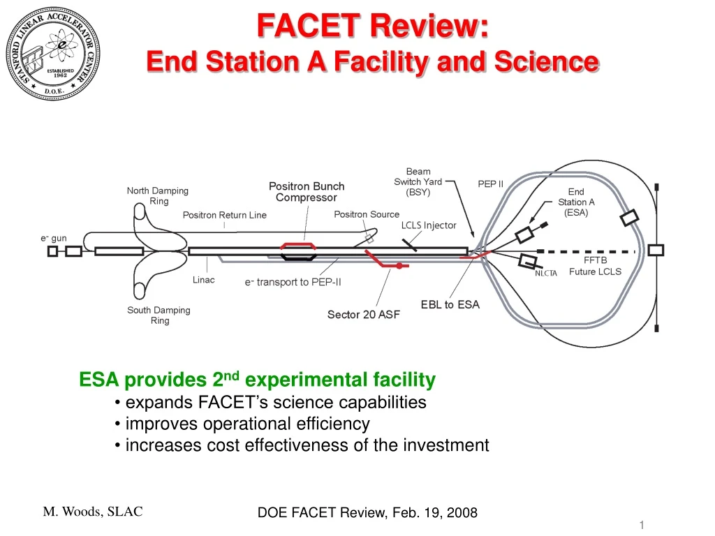
FACET Review: End Station A Facility and Science • ESA provides 2nd experimental facility • expands FACET’s science capabilities • improves operational efficiency • increases cost effectiveness of the investment
OUTLINE • End Station A Facility • Experimental Hall and Counting House • Operational Modes & Beam Parameters • Science • Accelerator science and beam instrumentation w/ primary electron beam • Activation, residual dose rates and materials damage studies w/ beam dump tests • Detector R&D using secondary electrons and hadrons • Particle Astrophysics Detectors and Techniques • Recent Experiments • ESA Program starting in 2011 → FACET-ESA provides unique science capabilities!
End Station A 2-Mile Linac
End Station A (ESA) • ESA is large (60m x 35m x 20m) • 50 (and 10) ton crane • Electrical power, cooling water • DAQ system for beam and magnet data
End Station A Facility and Experimental Layout in 2006-08 *Dimensions given in ft • Primary beam experiments inside concrete bunker • Beam dump experiments inside concrete bunker • (or in Beam Dump East beamline) • Secondary electrons for Detector Tests in open region • after the concrete bunker
ANITA Payload and Ice Target in ESA T-486 (2006) • Calibrated entire ANITA balloon flight antenna array; major contribution to the experiment! • First observation of the Askaryan effect in ice • Results published in Phys.Rev.Lett.99:171101,2007 • illustrates capability of ESA Test Beam Facility
ESA Science: Recent Experiments ILC Program 2006 – 2007 (+ 2008?) Detector R&D Particle Astrophysics Activation, Residual Dose Rates & Materials Damage Studies
Linear Colliders → ESA Program • Machine-Detector Interface at the ILC • (L,E,P) measurements: Luminosity, Energy, Polarization • Forward RegionDetectors • Collimation and Backgrounds • Interaction Region (IR) Engineering: Magnets, Crossing Angle • EMI (electro-magnetic interference) in IR • MDI-related Experiments at SLAC’s End Station A • Collimator Wakefield Studies • Energy spectrometer prototypes • IR background studies for IP BPMs • EMI studies • Beam Instrumentation Experiments in ESA • RF BPM prototypes for ILC Linac • Bunch length diagnostics for ILC
ILC Beam Tests in End Station A BPM energy spectrometer (T-474/491) Synch Stripe energy spectrometer (T-475) Collimator design, wakefields (T-480) Bunch length diagnostics (T-487) IP BPMs—background studies (T-488) LCLS beam to ESA (T490) Linac BPM prototypes EMI (electro-magnetic interference) + SiD KPiX Test during T-492 http://www-project.slac.stanford.edu/ilc/testfac/ESA/esa.html M. Woods, SLAC
ILC Beam Tests in End Station A • 50 Participants from 16 institutions at SLAC in 2006/07 for this program • Birmingham U., Cambridge U., Daresbury, DESY, Dubna, Fermilab, • Lancaster U., LLNL, Manchester U., Notre Dame U., Oxford U., • Royal Holloway U., SLAC, UC Berkeley, UC London, U. of Oregon Wakefield Studies from MCC T-474 and EMI Test Users in ESA Counting House
ESA Equipment Layout blue=FY06red=new in FY07 Wakefield box Wire Scanners “IP BPMs” T-488 rf BPMs 18 feet Ceramic gap for EMI studies T-487: long. bunch profile Dipoles + Wiggler • able to run several experiments interleaved in a compatible setup • typically rotate which experiment has priority every 2-3 shifts during a 2-3 week run
Prototype Energy Spectrometers BPM 4,7 Vertical Wiggler BPM 3,5 BPM 9-11 D2 D3 D4 D1 Energy Scan measured with Chicane BPMs BPM Energy Spectrometer U. Cambridge, DESY, Dubna, Royal Holloway, SLAC, UC Berkeley, UC London, U. of Notre Dame Synch Stripe Spectrometer U. of Oregon, SLAC • ILC needs precision energy measurements, • 50-200 ppm, e.g. for Higgs boson and • top quark mass measurements • BPM & synchrotron stripe spectrometers • evaluated in a common 4-magnet chicane. Wiggler synchrotron stripe Detector is downstream • For BPM spectrometer • dE/E=100ppm → dx= 500nm, • at BPMs 4,7 • Dipole B-field ~ 1kGauss • these are same as for ILC design
Prototype Linac RF BPMs S-Band BPM Design (36 mm ID, 126 mm OD) Q~500 for single bunch resolution at ILC 550nm BPM res. y4 (mm) y5 (mm)
Resolution & Stability: Linking BPM Stations in ESA BPMs 1-2 BPMs 3,5 BPMs 4,7 BPMs 9-11 Wake- Field Box x Run 2499-2500 Chicane region 30 meters • use BPMs 1,2 and 3,5 and 9-11 to fit straight line • predict beam position at BPMs 4 • plot residual of BPM 4 wrt predicted position *0.5mm → 100 ppm “error” bars shown are rms resolution y Run 2499-2500 Run 2499-2500 → investigating long-term (hours) stability at sub-micron level; study dependence on beam parameters and environment (temperature, magnetic fields) and electronics stability → stability studies important for Linac BPM and quad magnetic center stability requirements (also of interest for system of 40 RF BPMs for LCLS undulators)
Energy Spectrometers: Future Measurements & Tests Needed • BPM Spectrometer: • establish BPM calibration procedure and frequency • establish energy spectrometer calibration procedure and frequency • (requires reversing chicane polarity) • can luminosity be delivered during calibrations? • establish requirements for temperature stability, vibrations from water systems • Synchrotron Stripe Spectrometer: • still need to demonstrate proof-of-principle with quartz fiber detectors; • will need 24 GeV beam rather than 12 GeV beam • study concept using visible light detection; hope to test in 2008 • Both systems: • want to compare results from the 2 systems; do they agree? • is 50 ppm accuracy achievable? • tests evolve from concepts to prototypes to qualifying production components • → need tests prior to completion of ILC beam delivery system
2 doublets Two triplets BPM BPM BPM BPM ~40m 15m Collimator Wakefields Concept of Experiment Collimators remove beam halo, but excite wakefields. Goal: determine optimal collimator material and geometry → Beam Tests address achieving design luminosity → effects determine collimation depth and radius of vertex detector Collaborating Institutions: U. of Birmingham, CCLRC-ASTeC + engineering, CERN, DESY, Manchester U., Lancaster U., SLAC, TEMF TU Vertical mover
2 doublets Two triplets BPM BPM BPM BPM 1500mm ~40m 15m Collimator Wakefields Concept of Experiment Vertical mover
a = 166 mrad r = 1.4 mm Col. 12 Results from 2007 Data Col. 6 a = 166 r = 1.4 mm • Collimator 6 was also measured in Run 1, with consistent result. • Collimator 12 is identical to 6 for taper angle and gap, but it has a 2.1cm flat section • A total of 15 different collimator geometries were tested in 2006 and 2007 • (differing taper angles, gaps, length of flat sections, materials and surface • roughness)
Collimator Wakefields: Future Measurements & Tests Needed • Comparing with Analytic Calculations and 3-d modelling: • consistency with existing data varies from 10% level to a factor of • 2 disagreement depending on geometry • goal is to accurately model wakefield effects to 10% • in some cases better modeling is needed; but also need more accurate data • for some geometries as well as new data for different geometries and • materials • Broad interest in Wakefield tests: • relevant for linear colliders, LHC, low emittance light sources • Future measurements: • best done with low energy beams; desire for relatively low emittance • and short, well understood bunch lengths • bunch lengths may be too long for FACET-ESA to be very useful; • → can do these experiments at ASF • later upgrade for an RF gun at the injector would enable these tests in ESA • (+ in general an RF gun would add significant capability to ESA program, • providing significantly smaller transverse and longitudinal emittances)
Future development & tests needed: • 1000 channels • KPiX on new sensors • bump bonding • sensor resolution Detector Development • KPiX readout chip is being developed at SLAC for SiD concept. • 1000-channel ASIC design to read out entire Si wafer or pixel detector • Si-W ECal, Si Outer Tracker, GEM HCal, (Muons?) • 32x32=1024 channels; currently a 2x32 prototype • Pulsed-power operation delivers 20μW/channel average with ILC timing • 2007 beam test used 3 planes of Si (50 mm width) mstrip sensors • (spare from CDF Layer 00) ESA beamline setup KPiX Local DAQ board w/ FPGA; fiber bundle to detector, and USB to local PC w/ ethernet
Other Recent Experiments • Detector Tests: • T-469 (ESA 2006-7): Focusing DIRC for particle ID, and very precise TOF • detectors aimed at 10ps timing resolution (motivated by Super-B) • Radiation Physics and Materials Damage Tests: • T-489 (ESA 2007) – activation and residual dose rates of materials • compare with MARS and FLUKA simulation codes • T-493 (ESA 2007) – LCLS undulator beam-induced demagnetization studies • Particle Astrophysics Detectors and Techniques: • GLAST (ESA 2000) – LAT Tower (anti-coincidence detector, • silicon tracker and calorimeter) calibration and system integration • using secondary positrons, hadrons and tagged photons • FLASH experiment (2002-2004 in FFTB) measured • fluorescence yields in electromagnetic showers to help calibrate • air shower detectors for ultra-high energy cosmic rays (used primary beam) • Askaryan effect (FFTB 2002): demonstrated a radio Cherenkov signal • from Askaryan effect for detectors proposed to detect ultra-high energy • neutrinos; used primary electron beam • ANITA (ESA 2006): calibrated the entire balloon flight array and made the • first observation of the Askaryan effect in ice; used primary electron beam
T-489 Activation Experiment (CERN, SLAC collaboration) Analysis • gamma spectroscopy for many isotopes • residual dose rates versus time • tritium activity Setup
Future Activation and Materials Damage Studies • test different target materials • test different geometry configurations • instrumentation tests and calibration • radiation hardness for electronics and materials • broad interest for these studies in high radiation environments at different accelerators • needed for both accelerator and detector components
FACET-ESA Facility Operational Modes & Beam Parameters • Operational Modes: • ESA operation simultaneous with ASF using pulsed magnets • ESA access and experimental setup while ASF in operation • ASF access prevents beam to ESA, but can access ASF • for experimental setup during day and run ESA beam at night • Beam Parameters: • Primary Beam for Accelerator Science, Beam Instrumentation and • Beam Dump experiments • Secondary electrons and hadrons for Detector R&D
Primary Beam Parameters to SLAC ESA *24 GeV possible with later upgrade, moving extraction point to Sector 18
Secondary Electrons Insertable valve • Electron rates from single particle up to 105 per pulse • 2-10 GeV momentum range • precise (0.1%) momentum analysis using A-line as a spectrometer • rms spotsize in ESA ~3mm Production: insert a valve in EBL for a low intensity beam of ~109. Other possibilities: i) higher intensities of 12 GeV electrons: collimate a low intensity, large energy spread beam with A-line momentum slits (cover range from ~106 up to full intensity) ii) set A-line to accept positrons. (may be possible to design PPS to allow ESA occupancy during beam on operation?)
A-Line Hadron Production Facility Be Target: 0.43 r.l; 1.5-deg production angle PC28: 6 msr geometric acceptance C37: up to 11% momentum acceptance; adjustable Q38: corrects dispersion at detector in ESA Q29,Q30: control spotsize in ESA (ongoing studies indicate need for additional 2 quads in ESA; use Q29,Q30 for waist at C37). Expect to achieve ~1cm rms spotsize at detector location in ESA
Secondary Hadron Yields Measured and predicted (curves) particle fluxes of secondary beams from SLAC Report 160. (pulse length is 1.6 ms, so 1mA corresponds to 1010 electrons/pulse)
Secondary Hadron Yields 3.7 6 8 10 Naïve scaling for FACET (+ yields should be reduced by ~x2.5) Measured and predicted (curves) particle fluxes of secondary beams from SLAC Report 160. (pulse length is 1.6 ms, so 1mA corresponds to 1010 electrons/pulse) → expect rates up to ~10 pions/pulse per 1010 electrons on target → rates for kaons and protons x10-50 less
ESA Science Program starting in 2011 • 1. Linear Colliders, Accelerator Science & Beam Instrumentation • primary beam experiments • need to evaluate both cold (ILC) and warm (ex. CLIC) linear colliders; • ex. demonstrate beam instrumentation capabilities to resolve beam • parameter time dependence along a 200-300ns train • Experiments • BPMs + other typical accelerator instrumentation such as toroids • MDI components and instrumentation: • energy spectrometers, polarimeters, forward region detectors, luminosity • detectors, beam halo detectors • tests requiring large amount of space: mockups of IR components, • long baseline BPM or quad tests for vibration and stability studies • tests that don’t require ultra-small or ultra-short beams
Comparing Beam Parameters for FACET-ESA and Linear Colliders *24 GeV possible with later upgrade, moving extraction point to Sector 18 **long pulse operation can give 400-ns train with 0.3ns bunch spacing and total charge up to 5 x 10¹¹ (other bunch spacings may also be possible) • only place in the world to do this!
ESA Science Program starting in 2011 • 2. Advanced Detector R&D with secondary electrons and hadrons • Linear Colliders, LHC detectors, Super-B, … • large scale mockups and integration tests possible • precise momentum definition for electrons • precise timing • multiple particles coincident in time, and high-density electron rates possible • 3. Activation, Residual Dose Rates and Materials Damage Studies • additional data needed for accelerator and detector components • at linear colliders, LHC and light sources • data needed to tune and validate simulation codes such as MARS and FLUKA • data needed for environmental impact in high radiation environments • 4. Tests for Particle Astrophysics Detectors and Techniques • calibrating instruments and testing new detector concepts with test beams • will continue to be essential for experiments in high energy particle astrophysics The FACET-ESA facility will attract and service a wide range of users!
Summary of ILC Detector R&D Test Beam Needs (from “Roadmap for ILC Detector R&D Test Beams” document) + significant test beam needs for LHC upgrade, Super-B if it proceeds, … • CERN and Fermilab have the most capability for energy range and particle species • FACET-ESA at SLAC can provide an important additional U.S. facility
CERN PS/SPSTest Beams C. Rembser, CERN SPS: 4 Test Beamlines PS: 4 Test Beamlines 2007: Beam time requests from 47 groups, O(1500) users • SPS test beams: 23.5 weeks requested • ~52% LHC & LHC upgrade • ~35% external users • PS test beams: 28 weeks requested • ~43% LHC & LHC upgrade • ~12% external users
LHC Test Beam Experience (from P.Schacht at IDTB2007 Workshop) • Typically 3 phases of testbeam activities: • prototype tests • quality control + validation of performance requirements • full calibration of final calorimeter; wedge tests • Phase 2 hardware (read-out electronics, cabling, calibration) and software (reconstruction algorithms, calibration modes) should be close as possible to final • Phase 3 hardware and software have to be final versions • Transition regions – cracks between calorimeters, dead material, etc. – important: • optimize correction procedures, validate MC geometry + hadronic shower models ATLAS wedge test
Fermilab M-Test Beamline(from E. Ramberg at IDTB2007 Workshop) Tail Catcher HCAL Electronic Racks ECAL Spill structure • one (1-4)s spill every 2 minutes • possibility for 1ms “pings” • at 5Hz during spill • 3MHz bunch structure possible Beam ~6 m Plans for CALICE Setup
ESA strength ESA capabilities for Detector Beam Tests ESA satisfies many of the desired capabilities for a test beam facility
Summary • FACET provides unique capabilities w/ a high energy, high intensity electron beam • ESA provides a large flexible facility with excellent infrastructure to • accommodate a wide range of experiments: • accelerator science and beam instrumentation tests that do not require • spotsizes below 100 microns or bunch lengths below 1mm • advanced detector R&D with high quality secondary electron beams and a • general purpose pion beam; good applicability for a linear collider, for • LHC upgrades or for Super-B • beam dump experiments for activation, dose rate and materials damage studies • detector R&D for high energy astrophysics instruments • variable flux of electrons available from single particles to moderate intensities • for high rate detectors (ex. very forward BeamCAL detectors at a linear • collider) to full primary beam power • Inclusion of ESA in the FACET proposal broadens the science capabilities. • interleaved experiments in 2 facilities improve efficiency and cost effectiveness • choice to do experiments in ASF or ESA FACET can build on a long, rich history of successful test beam and small experiments in End Station A.
Transverse Beam Emittance to ESA no radiation (chromatic) input level (from DR) At 12 GeV, expect gex = 150 mm-mrad gey = 15 mm-mrad
Longitudinal Emittance to ESA LiTrack simulation results for bunch length and energy spread: Ne = 0.75∙1010 E = 12 GeV rms Energy Spread (%) rms Bunch Length (mm) Large R56 (=0.465m) for A-line and relatively large energy spread at low energy result in large bunch lengths in ESA.