Download
1 / 45
450 likes | 630 Views
CMS ME CSC HV system production readiness review. Alex Madorsky University of Florida. UF/PNPI HV system architecture. Distribution board 30. Master boards. Multiwire HV cables, 100 m, one per 18 distribution boards. Distribution board 36.

E N D
CMS ME CSC HV systemproduction readiness review Alex Madorsky University of Florida
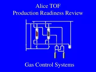
UF/PNPI HV system architecture Distribution board 30 Master boards Multiwire HV cables, 100 m, one per 18 distribution boards Distribution board 36 • Primary HV power supplies: off the shelf, one per distribution rack, 8 total • Master board: One output per distribution board. Regulates voltage 0-4KV (VMAX), measures current on each output. • Remote Distribution board: powers one large or two small chambers (36 outputs max). Regulates voltage 1KV down from VMAX, measures current on each output. Each output can be disconnected from HV if necessary. • Total number of individually controlled HV channels: 8856
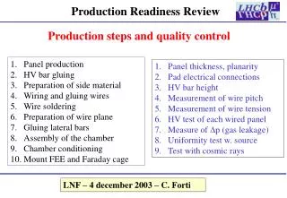
Distribution boards HV input Control connector HV outputs Power connectors • Each channel: • Controls voltage 1 KV down from input voltage • Measures output current • Two types of distribution boards: • 36 channels (two small chambers) – 139 boards • 30 channels (one large chamber) – 159 boards • Parts procurement, SMT assembly: UF • Final assembly and tests: PNPI
Master board Input HV 8 output HV connectors Control and LV power connector • Master board: • Each output drives one distribution board • Controls HV from 0 to 4KV on 8 outputs • Measures current on each output • Provides low negative voltage for fuse control circuit • 46 boards to produce • Parts procurement, SMT assembly: UF • Final assembly and tests: PNPI
Host card Xilinx JTAG connector, for FPGA configuration Control cable connector. PCI connector • 20 boards to produce • Parts procurement, assembly: UF • Tests: PNPI • Host card: • Sits in PCI bus of the control computer • Able to control up to 16 Distribution or Master boards
Scope of the production Total number of individually controlled HV channels: 8856 (spares not included, ME4/1 included) Production items (fan-out cables not included):
Overall production organization Project leader Project engineer Chamber group liaison Guenakh Mitselmakher Alex Madorsky Andrey Korytov UF Production coordinator Alex Madorsky See UF production diagram on page 10 PNPI Production coordinator Victor Golovtsov See PNPI production diagram in V.Golovtsov’s presentation
UF responsibility • Development and production management • Pre-production prototype construction and testing • Test stands construction • Test procedures verification, instructions • Off-the-shelf components procurement • Bare PCBs manufacturing • Automated SMT assembly • US labor and components contingency
UF production organization Production coordinator Alex Madorsky Distributors Assembly houses • Technician: • Arkadi Averbukh • Student assistants • Quality assurance (tests) • Repairs • Database maintenance • Shipping and handling Machine shops Software engineer: Victor Barashko Test software maintenance
UF Quality Assurance • Boards tested: • Distribution boards • Master boards • Visual test: • Presence of all components • Values • Orientation • Electrical test: • Control bus interface • DAC • ADCs • ID register • Results of all tests are inserted into production database
UF production status • All parts for Distribution, Master and Host boards are purchased • PNPI received all parts and equipment necessary to begin production • Remaining test stand equipment and all production components shipped to PNPI • Distribution boards: • 68 boards SMT-assembled • 68 SMT-assembled boards shipped to PNPI • Master boards: • 20 boards SMT-assembled • 4 SMT-assembled boards shipped to PNPI • Host cards: • all boards assembled • Distribution crate: prototype assembled and tested • Master crate: prototype assembled and tested • Test stand software development finished for Distribution and Master boards • Binary release and step-by-step instructions are available via web-page (along with other information): http://www.phys.ufl.edu/cms/emu/hv/ • Access to source code via CVS • Production database similar to chamber database is kept in text files
PNPI responsibility • Simple mechanical components manufactured • Pre-production and production manual assembly • Pre-production and production testing • PNPI labor and space contingency
PNPI test stand types • Regulator board test stand • Uncoated boards at 1KV • Coated boards at 4KV • Assembled Distribution and Master board test stand • Full parametric testing of assembled boards • Calibration • Voltage setting • Voltage measurement • Current measurement • Long term test stand • Burn-in • Parameter verification after burn-in • Total 11 tests for each board. Results of all tests are inserted into production database. • Most of the test stand components provided by UF. • More details on test stands in the presentation by V.Golovtsov.
PNPI production status • Completely assembled and tested: • 10 Distribution boards • 2 Master boards • PNPI production organization details to be shown in the presentation by Victor Golovtsov.
Database file for Distribution board (fragment) File name: DS001 Date : April 21 2004 Time : 10:00 Name : L.Sergeev Type : Assembly_full Comments : R00001,R00002,R00003,R00004,R00005,R00006,R00007, R00008,R00009,R00010,R00011,R00012,R00013,R00014, R00015,R00016,R00017,R00018,R00019,R00020,R00021, R00022,R00023,R00024,R00025,R00026,R00027,R00028, R00029,R00030,R00031,R00032,R00033,R00034,R00035, R00036,V001 Date : April 22 2004 Time : 10:00 Name : N.Isaev Type : Test Test : 1 Result : Fail Comment : Bad Test1 Date : April 22 2004 Time : 10:00 Name : S.Volkov Type : Diagnosis Reference : U32 Partnumber : ADS7818EB Comment : Bad chip Date : April 22 2004 Time : 10:00 Name : S.Volkov Type : Solution Reference : U32 Partnumber : ADS7818EB Comment : Replace chip • All records are in fixed format • Records are easy to import into production database • Production database is being developed
Test log file example (fragment) File name: T01_M001.log ======================================================== Test1 results 04-02-2004 18:33:20 Board ID001 30 channels HV Tests Software Ver.1.0 +5V 2493 - O'k -5V 1306 - O'k Interlock - On Point1- No data Point2 Voltages: 552 549 547 553 549 553 552 550 551 550 552 553 551 550 551 550 548 546 536 545 551 549 542 549 552 551 553 551 547 547 Channels: 1 4 6 7 9 11 12 13 15 21 25 26 27 28 Out of range 530 +/- 20 Currents: 2506 2514 2555 2552 2539 2546 2569 2539 2540 2517 2534 2537 2475 2513 2532 2520 2490 2558 2532 2561 2536 2524 2603 2461 2511 2540 2509 2545 2512 2551 Point3 Voltages: 801 798 797 801 798 801 800 798 801 798 800 802 799 798 799 799 797 795 785 794 799 797 791 795 800 798 801 800 796 795 Channels: 1 4 6 9 12 27 Out of range 780 +/- 20 Currents: 2502 2504 2544 2540 2531 2535 2558 2533 2537 2511 2530 2533 2473 2511 2529 2521 2489 2558 2531 2561 2535 2521 2599 2460 2511 2540 2509 2544 2512 2550 • Each test generates a log file • All relevant information is inserted into log file • Log file is appended if this test is run multiple times
Pre-production system tests • Minimal system segment • One primary power supply • One Master board • 8 Distribution boards • 288 channels • 8 chambers connected to Distribution boards • One of the chambers is connected to FAST DAQ • Parametric tests • Check if the system matches all specifications • See results on few next slides • Tests with chamber • Ground & Power configuration as close as possible to real detector • Results are in the presentation by A. Denisov
Pre-production system testsWiring diagram Primary HV source Regular HV fanout cables (Kerpen) Master board SHV cables FAST DAQ Distribution boards
Pre-production system testsGrounding diagram Compare with page 3
Test of specification requirements • Test result conclusions: • Pre-production system works fine in normal conditions. • In the conditions of very high humidity (above 80%) increased leakages were observed in some channels. Steps are taken to improve the system performance in high humidity conditions: • Coating process is modified to provide better coating quality • Triple coating • Slots are made in critical high-voltage gaps on PCBs • Quality assurance will include humidity chamber tests • Maximum current per channel without software trip: about 350 uA. Not a problem, according to Andrey Korytov.
Pre-production system tests with chambers FAST site HV Distribution rack simulation Control room simulation Disk with chambers simulation
Development in progress • Miscellaneous components are being developed in UF • Not critical for production • Patch panels for HV and control cables • See “Scope of production” slide for quantities • Finish by January ‘05 • Cables from Master boards to Distribution boards • Length to be defined, about 100 meters • HV cables • KERPEN halogen-free cables, same as Distribution-to-chamber cables • One prototype is assembled (120 m) • Production in CERN • Control cables • Amphenol Spectra-Strip halogen-free round-n-flat • See “Scope of production” slide for quantities • Finish by January ‘05 • Pending approval from “Cable committee” chaired by Gerard Faber • Internal Distribution and Master rack cables • HV cables – coaxial with SHV connectors, ~3 m (800 pcs) • Control cables – Flat twisted pair, ~3 m (60 pcs) • Finish by January ‘05
Low Voltage Requirements for Remote Distribution Cards • Low voltage power will be provided by CMS AC/DC LV system
Software • Linux driver for HostCard (V. Barashko, UF) • Multiple Host Cards • Multiple Distribution and Master boards • Main functionality finished • DIM server (V. Barashko, UF) • Works with Linux driver • Compatible with CERN slow control software (PVSS) • Main functionality finished • Chamber database (V. Barashko, UF) • In development • Operator interface program (V. Barashko, UF) • Simple text-mode version ready • GUI conceptual design underway • PVSS shell for slow control (Marina Giunta (CERN), Valery Sytnik (UC Riverside)) • Specification is in preparation in UF
HV system software structure Operator’s GUI PVSS application Control computer #2 Control computer #1 Control computer #3 Slave DIM server Main DIM server Slave DIM server PCI driver PCI driver PCI driver Chamber database Host cards Host cards Host cards
Field name Example Note Chamber name ME2/3-12 Real chamber name, as marked Segment number 3 Segment number in the chamber Action 23 Action code (set voltage, set trip current, set ramp up speed, etc.) Data field … Action-specific data in high-level units (voltage in volts, current in amperes, etc.). DIM server command example
HV system software reliability • Critical pieces of software: • PCI driver • DIM server • Critical software-dependent functionality: • Interlock • Trip • Software may crash for the variety of reasons: • Bugs • Power failure • Computer failure • Operator mistake • … • How to detect any possible software crush: • Hardware “watchdog” • Such devices are available for about $130 • What to do on software crush: • Kill primary HV power supply / supplies that are controlled by the crashed computer • Reset computer by turning power off and on
Operator shell screenshot • PCI:0:6, Card:0 dataslot:0, ioaddr:0xE2D8E000 • Module:0xd: state:OFF, type:RDB 36, ID:0, Chans:36, ILock:0 • Ch# Vmon Imon Vset Vcur RmpUp RmpDn Vmax Imax Vtrip Itrip Relay Fuse State Status • V mkA V V V V V mkA V mkA • --------------------------------------------------------------------------------------- • 01| 0 0.0 2752 0 18 18 4000 100 0 0 0 0 OFF OFF • 02| 0 0.0 2745 0 18 18 4000 100 0 0 0 0 OFF OFF • 03| 0 0.0 2745 0 18 18 4000 100 0 0 0 0 OFF OFF • 04| 0 0.0 2761 0 18 18 4000 100 0 0 0 0 OFF OFF • 05| 0 0.0 2757 0 18 18 4000 100 0 0 0 0 OFF OFF • 06| 0 0.0 2756 0 18 18 4000 100 0 0 0 0 OFF OFF • 07| 0 0.0 2756 0 18 18 4000 100 0 0 0 0 OFF OFF • 08| 0 0.0 2749 0 18 18 4000 100 0 0 0 0 OFF OFF • 09| 0 0.0 2754 0 18 18 4000 100 0 0 0 0 OFF OFF • 10| 0 0.0 2735 0 18 18 4000 100 0 0 0 0 OFF OFF • 11| 0 0.0 2748 0 18 18 4000 100 0 0 0 0 OFF OFF • 12| 0 0.0 2748 0 18 18 4000 100 0 0 0 0 OFF OFF • 13| 0 0.0 2742 0 18 18 4000 100 0 0 0 0 OFF OFF • 14| 0 0.0 2756 0 18 18 4000 100 0 0 0 0 OFF OFF • 15| 0 0.0 2761 0 18 18 4000 100 0 0 0 0 OFF OFF • 16| 0 0.0 2739 0 18 18 4000 100 0 0 0 0 OFF OFF • 17| 0 0.0 2748 0 18 18 4000 100 0 0 0 0 OFF OFF • 18| 0 0.0 2741 0 18 18 4000 100 0 0 0 0 OFF OFF
Distribution board • 36 channels (two small chambers) – 139 boards • 30 channels (one large chamber) – 159 boards
Master Board • 46 boards to produce
Host Card • 20 boards to produce
1KV regulator • 10,072 boards to produce
4 KV regulator • 400 boards to produce
HV Relay board • 400 boards to produce
Distribution crate • Made from standard ELMA parts, except side panels (custom length) • Houses 9 distribution boards • No backplane • 30 crates to make • Parts procurement: UF • Assembly: CERN
HV Distribution Crate • 30 crates to produce
Distribution Rack Fan unit & heat exchanger • Need from CMS: • Racks • Fan units & heat exchangers • Strain reliefs • Space in front and behind the racks • Low Voltage power for distribution boards Distribution crate Distribution boards HV and control cables patch panel Output HV cables to chambers