Download
1 / 26
290 likes | 518 Views
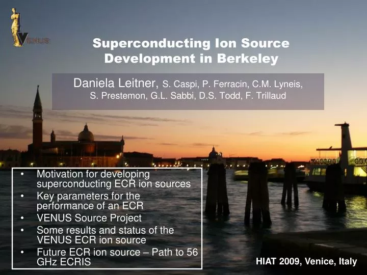
Superconducting Ion Source Development in Berkeley. Daniela Leitner, S. Caspi, P. Ferracin, C.M. Lyneis, S. Prestemon, G.L. Sabbi, D.S. Todd, F. Trillaud. Motivation for developing superconducting ECR ion sources Key parameters for the performance of an ECR VENUS Source Project

E N D
Superconducting Ion Source Development in Berkeley Daniela Leitner, S. Caspi, P. Ferracin, C.M. Lyneis, S. Prestemon, G.L. Sabbi, D.S. Todd, F. Trillaud • Motivation for developing superconducting ECR ion sources • Key parameters for the performance of an ECR • VENUS Source Project • Some results and status of the VENUS ECR ion source • Future ECR ion source – Path to 56 GHz ECRIS HIAT 2009, Venice, Italy
ECR ion sources have made remarkable improvements over the last few decades, but the demand for increased intensities of highly charged heavy ions continues to grow Supermafios (Geller, 1974) 15 eµA of O6+ VENUS (2007) 2850 eµA of O6+ Factor 200 increase VENUS, FRIB MSU, USA SC-ECRIS, RIKEN, Japan SPIRAL 2, GANIL, France 270 eµA U33+ and 270 eµA U34+ 525 eµA U35+ 1mA Ar12+
The demonstrated VENUS source performance shows that these ion beam intensity requirements are possible High Intensity Uranium Production 6kW 28 GHz 770 W 18 GHz Required temperature of 2100 C in a 4 T B field
Minimum-B field Confinement SolenoidCoils e- heating µwave gas ions Sextupole Higher magnetic fields and higher frequencies are the key to higher performance neωrf2 qoptlog ω3 Resonant electron heating e•B we= = wrf m ECR (1983) 0.4 T, 0.6 kW, 6.4 GHz AECR-U (1996) 1.7 T, 2.6 kW, 10 + 14 GHz VENUS (2001) 4.0 T, 14 kW, 18 + 28 GHz
Higher magnetic fields and higher frequencies are the key to higher performance VENUS 56 GHz predicted Normal conducting VENUS 28 GHz AECR 14 GHz Analyzed beam current [eµA] ECR 6 GHz Super conducting ne$ Argon Charge States ECR (1983) 0.4 T, 0.6 kW, 6.4 GHz AECR-U (1996) 1.7 T, 2.6 kW, 10 + 14 GHz VENUS (2001) 4.0 T, 14 kW, 18 + 28 GHz
Challenges • Superconducting Magnet • Cryogenic Technology • X-rays from the Plasma • Ion Beam Transport
Superconducting Magnets: ECR Design ‘Standard Model’ 56 GHz 28 GHz 8T 1-1.6 T 4T 4T 2T Binj ~ 4 ∙ Becr Bmin ~ 0.8 Becr Bext ~ Brad Brad ≥ 2 Becr Becr 4T .5-.8 T 2T 2T 1T
Superconducting Magnet Structure 56 GHz: two options Sextupole-in-Solenoid Geometry (VENUS) Solenoid-in-Sextupole Geometry (SECRAL) • Minimizes the peak fields in the sextupole coils • Strong influence (forces) of the solenoid field on the sextupole ends • Minimizes the influence of the solenoid on the sextupole field • Significantly higher field required for the sextupole magnet surface due to the larger radius of the coils • Strong forces on the solenoid coils
Superconducting Magnet 56 GHz: Magnetic Analyses Critical line and magnet load lines: NbSn3 NbSn3 Current Density through the superconductor Magnetic Field on the conductor
Superconducting Magnet Structure: Magnetic Analyses Goal: Achieve 4.2T on the plasma chamber wall radiallyand 8 T and 4 T on axis Solenoid-in-Sextupole Current Density through the superconductor • Magnetic field and current density requirements exceed the capability of NbSn3 Magnetic Field on the conductor This geometry can be ruled out as candidate for a 56 GHz ECR ion source
Superconducting Magnet Structure: Magnetic Analyses Goal: Achieve 4.2T on the plasma chamber wall radiallyand 8 T and 4 T on axis Sextupole-in-Solenoid Current Density through the superconductor • 2.5 Kelvin temperature marginfor the Sextupole • Operates at 86% of current limits Magnetic Field on the conductor This geometry is challenging but feasible with current NbSn3 technology
Sextupole-in-Solenoid: Clamping Structure Maximum peak field on the coil (15.1 T, 862 A/mm2 ) There are two limits to the maximum achievable field with this design Maximum force on the end point (up to 175 MPa) • To control these forces • In the end region each layer is subdivided in two blocks of conductors separated by end-spacers. • The number of turns per block and the relative axial position of the end spacers were optimized to reduce the peak field in the end region. • The coils are lengthen to reduce the peak field • Shell type support structure
Sextupole-in-Solenoid: Sextupole Magnet • 4-layer coils using cables (675 conductors/coil) • The same cable design is currently used by the LARP program to develop high field quadrupoles for future LHC luminosity upgrades (peak fields 15 T) A practice coil winding for the LARP quadrupole (HQ) • The cable design requires high 8.2kA current leads, the 56 GHz cryostat will most likely require He filling during operation.
Sextupole-in-Solenoid: Clamping Structure • A shell-based structure using bladders and keys provides a mechanism for controlled room temperature pre-stress. • Pre-stress is then amplified by the contraction of an aluminum shell during cool-down. • The method was developed at Superconducting magnet group at LBNL and successfully applied to high field magnets. • 2D cross section structure analyses has been conducted on the two critical regions • Stress values are close to the maximum acceptable values • Needs full 3D analyses
Quench protection Passive Quench Protection Burned Lead HTC leads • Energy stored in the VENUS magnet is 800kJ • VENUS coils do not require active quench protection • Leads need protection for adequate cooling • Energy stored in the 56 GHz Magnet 5.5MJ • Active Quench protection with heaters at the coils (75% coverage, results in peak temperatures in the coil of 280K) • Lead protection (Lesson from the VENUS quench failure) LN LHe Sol 1 Sol 3 Sol 2 Sextupole Coil Sol 1 Sol 3 Sol 2 Spliced sextupole lead wire
Other Challenges • Superconducting Magnet • Cryogenic Technology • X-rays from the Plasma • Ion Beam Transport
Cold Masswith Coils Enclosed Plasma A major challenge for high field SC ECR ion sources is the heat load from bremsstrahlung absorbed in the cryostat Technical Solution VENUS Aluminum Plasma Chamber with 2mm Ta x-ray shield HV Insulator 2mm Tantalum X-ray Shield Cold Masswith Coils Enclosed Water Cooling Grooves at the plasma Flutes
A major challenge for high field SC ECR ion sources is the heat load from bremsstrahlung absorbed in the cryostat without shield HV Insulator 2mm Tantalum X-ray Shield with shield Water Cooling Grooves at the plasma Flutes 1.5 - 2 mm Ta shielding effectively attenuates the low energy bremsstrahlung, but becomes transparent for x-rays above 400keV The high energy tail of the x-ray spectrum increases substantially at the higher microwave frequency (10s of ) watts of cooling power must be reserved for the cryostat.
Beam emittance grows with magnetic field at extraction (therefore with heating frequency) Beam transport is a challenge for high field SC ECR ion sources
Beam transport is a challenge for high field SC ECR ion sources Todd et al., Rev. Sci. Inst. 79 02A316
10 cm Simulation of oxygen beam extraction and transport Simulation Experiment O7+ O7+ Experiment Todd et al., Rev. Sci. Inst. 79 02A316
The requirements of the next generation heavy ion accelerator continue to drive ECR ion source development Higher magnetic fields and higher frequencies are the key to higher performance 200eµA of U33+ and U34+ have been produced, high temperature oven development is key for long term production 56 GHz ECR ion source magnet structures are feasible with current NbSn3 technology Development should start now to be ready for operation in 5-10 years Understanding of the plasma physics and the beam transport is important for the design of the next generation superconducting ECR ion sources Summary
Magnetic flux line e f=28 GHz, B= 1T rLamor=0.01…1 mm Key parameters for an ECR ion source performance Solenoids and Sextupole form a minimum-B field confinement structure Plasma is resonantly heated with microwaves we= = wrf e•B e- heating µ-wave m Plasma IONS gas
Superconducting Magnets: ECR Design ‘Standard Model’ 28 GHz VENUS Tune Binj ~ 4 ∙ Becr Bmin ~ 0.8 Becr Bext ~ Brad Brad ≥ 2 Becr
BECR Superconducting Magnets: ECR Design ‘Standard Model’ 28 GHz BECR= 1 Tesla 56 GHz BECR= 2 Tesla 56 GHz 28 GHz 8T 1-1.6 T 4T 4T Binj ~ 4 ∙ Becr Bmin ~ 0.8 Becr Bext ~ Brad Brad ≥ 2 Becr 4T .5-.8 T 2T 2T
The high energy tail of the x-ray spectrum increases substantially at the higher microwave frequency without shield with shield The scaling of the electron energy temperature with frequency has important consequences for 4th generation superconducting ECR ion source with frequencies of 37GHz, 56GHz. Several (10s of ) watts of cooling power must be reserved for the cryostat.