Download
1 / 22
240 likes | 420 Views
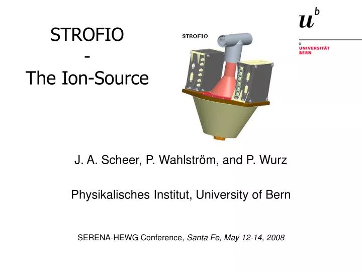
STROFIO - The Ion-Source. J. A. Scheer, P. Wahlström, and P. Wurz Physikalisches Institut, University of Bern SERENA-HEWG Conference, Santa Fe, May 12-14, 2008. SIMION Simulations. Neutrals. Ions. SIMION model of the ion source

E N D
STROFIO-The Ion-Source J. A. Scheer, P. Wahlström, and P. Wurz Physikalisches Institut, University of Bern SERENA-HEWG Conference, Santa Fe, May 12-14, 2008
SIMION Simulations Neutrals Ions • SIMION model of the ion source • One-source model because of background suppression (outgassing from satellite) • Simulations and calculations showed that background suppression is critical • Second source would measure mostly outgassing of spacecraft • Background suppression not possible for second source SERENA-HEWG Conference, Santa Fe, May 12-14, 2008
SIMION Simulations 120V 200V Electrons Ions SIMION model of ionization chamber with extraction electrodes Ionization rate: 0.0156 per particle s-1 cm-3 SERENA-HEWG Conference, Santa Fe, May 12-14, 2008
SIMION Simulations • SIMION model of ion source with potential arrays. • Red lines: potential difference 16V • Yellow lines: potential difference less than 1V SERENA-HEWG Conference, Santa Fe, May 12-14, 2008
SIMION Simulations 400 mm -790V -123V -46V 3D-view of the SIMION model of the ion source with trajectories of 90000 ions Software optimizer (voltages and geometry) works with full range of ion trajectories and adjustable spot size SERENA-HEWG Conference, Santa Fe, May 12-14, 2008
SIMION Simulations 195.67V -622V -70V 400V 312V 99V -120V -17V 22V 120V -316V 200V -424V 198.95V • SIMION model of ion source with trajectories of 90000 ions • Voltages taken from simulation for 976eV particles • Grids in ionization chamber to suppress background from spacecraft (i.e. very low-energy ions) 664V -65V -46V SERENA-HEWG Conference, Santa Fe, May 12-14, 2008
Results of SIMION Simulations The figure shows the effect of different grid voltages in the ionization chamber. Red graph demonstrates suppression of low-energetic background (outgassing) from spacecraft. Settings of red graph were used for all following simulations. SERENA-HEWG Conference, Santa Fe, May 12-14, 2008
Results of SIMION Simulations • Various transmissions simulated for different exit openings with constant particle energy. • The trend of higher transmissions for larger openings is clearly seen. • The increase of a factor of 2 for the opening diameter results roughly in a factor of 3 higher transmission. SERENA-HEWG Conference, Santa Fe, May 12-14, 2008
Results of SIMION Simulations Transmissions for different settings of the ion optics, which lead to different particle energies at the exit. The increase of transmission due to increased particle energy at the exit is small but gets more pronounced towards higher initial energies. SERENA-HEWG Conference, Santa Fe, May 12-14, 2008
Calculations Maxwell-Boltzmann Distributions for various expected components. Particle densities are taken from the ROSETTA mission (black and red lines) to simulate spacecraft gas. Particle densities are taken from Wurz and Lammer (2003) (green lines) for Mercury‘s exosphere. The distributions of H2 originating from Mercury (green) are shifted according to the satellite‘s velocity of 3000m/s. Note the overlap of Hydrogen from the spacecraft (black) with Hydrogen from Mercury (green). SERENA-HEWG Conference, Santa Fe, May 12-14, 2008
Calculations: H2 Black lines: Maxwell-Boltzmann distributions. Red and green lines: Fractions of these distributions of detected particles, red line is outgassing from satellite. Result: H2 can be measured. SERENA-HEWG Conference, Santa Fe, May 12-14, 2008
Calculations: H Black lines: Maxwell-Boltzmann distributions. Red and green lines: Fractions of these distributions of detected particles, red line is outgassing from satellite. Result: H cannot be measured. SERENA-HEWG Conference, Santa Fe, May 12-14, 2008
Calculations: Na Particle density of photon-stimulated desorbed Na relative to outgassing of spacecraft. Significant overlap only with light atoms and molecules, i.e. H and H2. Hydrogen and Na can be easily separated in the detector. SERENA-HEWG Conference, Santa Fe, May 12-14, 2008
Calculations: Ca Particle density on detector of sputtered calcium => Expected countrate 1 per 8 min SERENA-HEWG Conference, Santa Fe, May 12-14, 2008
Particle Densities on Detector SERENA-HEWG Conference, Santa Fe, May 12-14, 2008
The Ion-Source Prototype Filament Ionization chamber with grids and extraction electrodes SERENA-HEWG Conference, Santa Fe, May 12-14, 2008
The Ion-Source Prototype SERENA-HEWG Conference, Santa Fe, May 12-14, 2008
Calibration Facilities STROFIO: CASYMIR (Calibration System for the Mass spectrometer Instrument Rosina) http://www.space.unibe.ch/rosina/casymir/cas_SS.html ELENA: MEFISTO (MEsskammer fürFlugzeitInStrumente und Time-Of-Flight) http://www.space.unibe.ch/mefisto/ SERENA-HEWG Conference, Santa Fe, May 12-14, 2008
STROFIO Calibration: CASYMIR Facility The scope of the CASYMIR project (Calibration System for the mass spectrometer instrument Rosina) is the development of a calibration chamber with the aim of testing and calibrating space mass spectrometers. The spectrometers are part of the ROSINA Instrument package, which is one of the key experiments of the Rosetta mission planed by the European Space Agency ESA. The orbiter will accompany the comet Wirtanen on it's way to the sun. (Launch: 2003, End of mission: 2013). The two mass spectrometers (DFMS and RTOF), which are the main part of the ROSINA instrument package, will analyze the elemental, isotopic and molecular composition of the neutral and ionizes atmosphere of the comet Wirtanen. In order to simulate these conditions of the comet surroundings, CASYMIR consists of a vacuum system with several stages leading to a high vacuum, and a supersonic molecular beam with embedded thermal ions. CASYMIR will be designed and set-up at the Space Research & Planetary Sciences research division at the Physikalisches Institut of the University of Bern, Switzerland.The mass spectrometers will be calibrated in a static as well as in a dynamic mode. In the static calibration mode, a static atmosphere is introduced into chamber V1 and V0 in a pressure range of 10-6 to 10-10 mbar. SERENA-HEWG Conference, Santa Fe, May 12-14, 2008
STROFIO Calibration: CASYMIR Facility SERENA-HEWG Conference, Santa Fe, May 12-14, 2008
Spokes Lo-res Lo-res Hi-res Calibration of Instruments for Detection of Energetic Neutral Atoms (ENA) in SpaceJ.A. Scheer (1), L. Saul (1), P. Wurz (1), E. Moebius (2), E. Hertzberg (3), S.A. Fuselier (3), D.J. McComas (4), and the IBEX-Team(1) University of Bern, Physikalisches Institut, Sidlerstrasse 5, 3012 Bern, Switzerland(2) University of New Hampshire, Department of Physics and Institute for Study of Earth, Oceans and Space, Durham, New Hampshire 03824, USA(3) Lockheed Research Laboratories, 3251 Hannover Street, Palo Alto, California 94304, USA(4) Southwest Research Institute, San Antonio, Texas 78238, USAcorresponding authors: juergen.scheer@space.unibe.ch, peter.wurz@space.unibe.ch The MEFISTO Calibration Facility The Surface Neutralizer The Calibration of IBEX-Lo MEFISTO is a versatile ion beam calibration facility for characterization of space plasma instrumentation, in particular solar wind and supra-thermal particle instruments. With help of a surface neutralizer or a gas neutralizer, energetic neutral atoms can be produced as well. Ions are produced in an homemade Electron-cyclotron resonance ion source and extracted with 3kV. With post-acceleration they can reach an energy up to 100keV/q. The ion optic consists of several lenses and deflection plates, a Wien-filter and an electrostatic analyzer. The beam size is adjustable from 0.1mm to 8mm diameter, and the distance from ion beam exit to instrument inlet is about 1m. The vacuum system is bakeable up to 300°C and the shroud inside the vacuum chamber can be filled with liquid nitrogen. The instrument cooling plate is temperature controlled from -80°C to +150°C. After bakeout, the vacuum chamber reaches a base pressure of 1x10⁻⁸ mbar, with use of the cryo shroud the pressure goes down 5x10⁻⁹ mbar. The instruments are mounted on a hexapod-table, which allows the instruments to be moved within 5 degrees of freedom. With the alpha-stage (see picture bottom right) the possible movements increase to 6 degrees of freedom. With the prototype of the gas neutralizer (see picture below) energetic neutral atoms (ENA) of hydrogen and oxygen have been successfully produced in an energy of 500eV to several keV. For the future it is planned to extend this energy range to lower energies. The surface neutralizer enables us to produce ENAs in an energy range of 10eV up to several keV. For details, see the middle part of the poster. For measurements in space, background induced by UV-irradiation is a serious issue. Therefore, MEFISTO has been equipped with a sun-like UV-lamp to calibrate instruments for UV-irradiation. The intensity of the UV-lamp is approximately 1015 photons per cm2 per second at a wavelength of 126nm [1] M. Wüest, D.S. Evans, and R. von Steiger (Eds.), “Calibration of Particle Instruments in Space Physics”, ISSI Scientific Report SR-007 The IBEX-Lo Instrument The sole, focused science objective of the IBEX mission is to discover the global interaction between the solar wind and the interstellar medium. IBEX achieves this objective by taking a set of global energetic neutral atom (ENA) images. IBEX-Lo was designed to sense ENA in an energy range of 10eV to 2keV. We found that the only viable technique to do so in space is surface ionization, i.e. incoming neutral particles get ionized upon scattering from a conversion surface and in the following analyzed by the usual mass spectrometric means. This technique requires of course a thorough calibration, especially for the ENA to ion conversion process. Thus, a lot of work has been done to find suitable surfaces [3, 4] and to calibrate them [5]. [3] J.A. Scheer et al, Nucl. Instr. and Meth. B 230 (2005) 330 [4] J.A. Scheer et al, Adv. Space Res. 38 (2006) 664 [5] P. Wahlström, “Calibration of Charge State Conversion Surfaces for Neutral Particle Detectors”, submitted to Journal of Applied Physics IBEX-Lo IBEX-Hi Front view of the MEFISTO calibration facility. Left: instrument chamber, residual gas analyzer (black box). Middle: roughing pump, beam monitor, and gate valve. Right: ion source cabinet and electronics rack. From: [1] The Surface Neutralizer described here is already the third version built. Details about the previous versions can be found in [2]. The first thing you need to have to calibrate a neutral particle sensing instrument is a neutral particle beam. There are different approaches, such as neutralizing an ion beam with help of a crossing laser beam or neutralizing an ion beam on its way through a gas filled volume via charge exchange with gas atoms but none of these methods were suitable for our purpose. Neutralizing with a laser, for instance, needs a dedicated setup, whereas we were looking for a simple way to extend our already existing facility. And a gas neutralizer works for 200eV and higher energies, but we were interested in an energy range of 10eV-2keV. Thus, we had to find another solution, and the answer was surface neutralization, which will be explained in the following paragraph. Ions enter the surface neutralizer with a given energy of several keV. The desired energy is determined with a voltage applied to the deceleration stage. After passing an electrostatic analyzer the ions hit the neutralization surface, where most of the ions are converted into energetic neutral atoms (ENA). Any ions that survived the scattering process will be deflected by the deflection plates to make sure that only ENAs will leave the surface neutralizer. Below and right there are examples of data taken during the calibration of the surface neutralizer. Figures 1 and 2 show horizontal and vertical profiles of a neutral oxygen beam for different distances from the surface neutralizer exit. Figure 3 shows a calibration function for the flux of neutral hydrogen relative to the ion current measured on the neutralization surface. This function got derived from several independent measurement series, labeled as a1, a2, … Figure 4 shows this calibration function for three different species, i.e. oxygen, helium, and hydrogen. [2] M. Wieser and P. Wurz, Meas. Sci. Technol. 16(2005) 2511 The payload of IBEX is extremely simple with only two single pixel sensors and a single Combined Electronics Unit (CEU). The overlap of the energy range between IBEX-Hi (300eV – 6keV) and IBEX-Lo (10eV – 2keV) maximizes statistics and allows for in-flight cross-calibration, and provides imaging via two completely independent sensors across the most critical energy range for achieving the IBEX science objective. Taken from: http://www.ibex.swri.edu/index.shtml, for more information please contact Principal Investigator Dave McComas: dmccomas@swri.org Setup for calibration of the Surface Neutralizer. Left: Surface Neutralizer Middle: SSL detector Right: homemade highly sensitive pico-ammeter with integrated A/D-converter. The measurement range is 10nA to 0.01pA. • Calibration at the MEFISTO facility of the University of Bern • Most of the calibration of IBEX-Lo was done at the University of Bern, with the exception of acoustic tests at IABG in Munich and more UV testing as well as cross-calibration between IBEX-Hi and IBEX-Lo at SwRI in San Antonio, TX. • Three examples of data derived from the calibration measurements at the University of Bern are shown below: • The energy range, in which IBEX-Lo works, is divided into 8 discrete energy bins, which are each separated by a factor of 2. Figure 5 shows the energy response of each energy bin. • An azimuth scan (i.e. rotation within the alpha-stage) is displayed in Fig. 6. Several dips of the efficiency are clearly seen, when the ion beam illuminates spokes or the high-resolution section, which has lower transmission. • During the ENA to ion conversion process some particles are inevitably sputtered from the conversion surfaces and a fraction of these sputtered particles is eventually detected. This fraction is shown in Fig. 7. Front view of ECR ion source. Left: 2.45 GHz ECR ion source. Middle: Wien filter. Right: 180° energy analyzer. The whole cabinet can be floated up to 100 kV. From: [1] Left: Surface Neutralizer Middle: IBEX-Lo instrument inside the alpha-stage, which is mounted on the hexapod-table. The instrument has been turned 180° away from the ion beam to face the UV-lamp. Right: housing of UV-lamp with black aperture plate. Fig. 3 Testing of a prototype of the gas neutralizer. Left: gas neutralizer housing including deflection plates to deflect non-ionized particles. Right:: hexapod-table with faraday-cup to monitor the ion beam and SSL-detector to record the distribution of neutral particles. View of the inside of the instrument chamber. The grey area is the cryo shroud. The ion beam enters the chamber from the left hand side, the UV-lamp is mounted opposite on the right hand side. In the middle you can see the circular alpha-stage, which allows the instrument to be turned ±180° around the ion beam axis and thus results in a total of six degrees of freedom for the instrument’s movement. The hoses from above are connected to the cooling (or heating) plate. Fig. 5 Fig. 6 Fig. 7 Fig. 1 Fig. 2 Fig. 4
Summary and Outlook • One-source design optimal to suppress background. • Up to now, with the exception of H, all expected elements or compounds seem to be measurable with the chosen setup. • Very important: In-flight calibration to identify background! • Design and construction of ion-source prototype finished. Ready for manufacturing. • Input from detector-team essential for progress! • Measurements with ion-source prototype are scheduled for August 2008. SERENA-HEWG Conference, Santa Fe, May 12-14, 2008