Download
1 / 22
260 likes | 404 Views
SNICS Ion Source. Larry Lamm, Research Professor, Technical Director March, 2009 Nuclear Science Laboratory. MC-SNICS Ion Source. M ulti- C athode S ource of N egative I ons by C esium S puttering. Old SNICS Ion Source.

E N D
SNICS Ion Source Larry Lamm, Research Professor, Technical Director March, 2009 Nuclear Science Laboratory
MC-SNICS Ion Source • Multi- • Cathode • Source of • Negative • Ions by • Cesium • Sputtering
Old SNICS Ion Source • 1989 – 2008 SNICS II manufactured by National Electrostatics Corp. (NEC). • Primary ion source for the FN Tandem accelerator, producing all the ion beams for injection into the FN Tandem other than helium beams.
Old SNICS Ion Source • Extremely reliable • Often days of stable, continuous beam production from a single cathode • Changing cathodes can be time consuming • Not suitable for AMS program (Atomic Mass Spectroscopy)
MC-SNICS • Installed in 2008 to anticipate the needs of the AMS program • Same principles of operation as the SNICS II source • Designed to allow users to easily choose from up to 40 different cathodes
MC-SNICS • Source shown here in open position, suitable for loading a new cathode wheel • Well designed • Our experiences have been very good
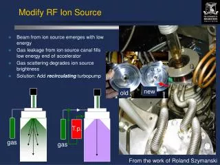
How does SNICS work? • A reservoir of cesium metal is heated to approximately 120 °C, so that cesium vapor is formed. • This vapor rises from the reservoir in vacuum to an enclosed region between the cathode, which is cooled, and the ionizer, which is heated.
How does SNICS work? • Some cesium condenses onto the cool surface of the cathode, while some comes in contact with the hot surface of the ionizer and is immediately "boiled away". • These positively charged cesium ions leaving the ionizer are accelerated toward and focused onto the cathode, sputtering material from the cathode at impact.
SNICS Ion Source • Some of the sputtered material gains electrons in passing through the cesium coating on the surface of the cathode, and forms the negatively charged beam.
SNICS Ion Source • Since the entire source is operated at approximately 80 kV below ground, this negative beam is accelerated out of the source and is available for injection into the FN Tandem accelerator.
MC-SNICS • Here you can see the circular disk that contains the cathodes • Standard versions – 20 element disks and 40 element disks. • 20 element disk, larger cathodes, general purpose usage
MC-SNICS • 40 element disk suitable for AMS work • Very small cathodes • We have not tried this yet.
MC-SNICS • Our installation • Required very minor changes to old facility • Re-used many of the existing power supplies, etc.
MC-SNICS • 40 element cathode disk • Never used • 20 element disk (not shown) is similar, but holds much larger cathodes • Easier to load material and easier to use
MC-SNICS • 20 element disk • It’s rough in there! • Cathodes can be loaded with a variety of powders, packed to fill the cavity in the cathode blank.
MC-SNICS Ion Source • Partial list of some of the beams recently produced by our MC-SNICS source. • Often make more beam than we can use, sometimes limited by amount FN Tandem can accept.
MC-SNICS Ion SourceComputer Control • The Nuclear Science Laboratory has established computer-based systems to allow for monitoring and control of many of the active systems within the laboratory. • This work is continuing, taking care to continue to provide a "hands-on" experience for our students while at the same time upgrading our control and monitoring systems. • Complete remote computer control of the MC-SNICS Sputter Ion Source has been established.
MC-SNICS Ion SourceComputer Control • Originally, the SNICS II Sputter Ion Source was operated manually, using insulating rods connected to the control dials of the various power supplies, so that the source could be safely adjusted by an operator at ground potential while the source was at 80 kV below ground. We can still operated in this manner, if desired, but we now almost always operate by remote computer control. • Our control system to allow for remote control operations of the MC-SNICS source is known as Group3 with ControlNet, a fibre optically linked control system using distributed I/O modules, available from GMW Associates, Inc.
SNICS Ion SourceComputer Control • Our control system to allow for remote control operations of the MC-SNICS source is known as Group3 with ControlNet, a fibre optically linked control system using distributed I/O modules, available from GMW Associates, Inc.
MC-SNICS Ion SourceComputer Control • Shown here an older front panel image of the LabVIEW program being used to control the MC-SNICS Ion Source. • You’ll see how to use this software later in the school.