Download
1 / 20
210 likes | 492 Views
Ion Source and RFQ. Douglas Moehs Fermilab Accelerator Advisory Committee May 10 th – 12 th , 2006. Thanks to Martin Stockli (SNS), Robert Welton (SNS), Jens Peters (DESY), and Jim Alessi (BNL) for providing study time on their respective ion sources.

E N D
Ion Source and RFQ Douglas Moehs Fermilab Accelerator Advisory Committee May 10th – 12th , 2006 Thanks to Martin Stockli (SNS), Robert Welton (SNS), Jens Peters (DESY), and Jim Alessi (BNL) for providing study time on their respective ion sources. Thanks to Chuck Schmidt and Henryk Piekarz for their contribution to ion source development Thanks to Giorgio Apollinari, Gennedy Romanov, and Peter Ostroumov for providing slides and detailed information regarding the RFQ.
Outline • RFQ R&D • LEBT • H- Ion Source • Meson Installation • Blended into other sections
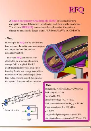
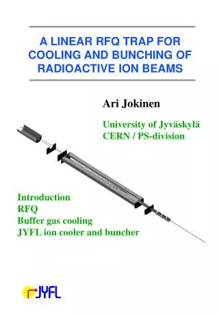
RFQ R&D • RFQs are standard devices for H- Linacs (J-PARC, SNS). • Strong focusing • Beam Bunching • Acceleration 50 KeV to 2.5 MeV • Commercial manufacturing is routine • An ANL - FNAL collaboration produced: • FNAL document 5500-ES-371025 • P. Ostroumov, V. N. Aseev and A.A. Kolomiets, IoP, 2006 JINST 1 P04002
RFQ REQUIREMENTS OPERATING REQUIREMENTS These parameters effect ion source and LEBT choices Halo free to reduce beam losses
RFQ R&D – Beam Dynamics Horizontal axis is input current. The Model assumes the input current emittance is fixed % Transv. Emit. Growth Output Beam Current Beam envelope along RFQ simulation (TRACK code), lower curves are beam RMS size, upper curves are beam envelopes for X and Y. Total particle loss is below 2% Figures provided by Peter Ostroumov, IoP 2006 JINST 1 P04002
RFQ – Prototype Procurement • Quote requests were sent to several manufacturing companies in ~Sept. 05 • Fermilab received several quotes in the ~0.5 M$ range and production schedules ranging from 6-12 months. • A 0.5 M$ requisition was placed in Jan ’06 and 3 bids were returned in March 06. • Companies had the option to adopt ANL/FNAL design or propose their own design meeting FNAL Beam specs. • Vacuum Chambers and Power Couplers were included in the order • Companies were also requested to provide quote for commissioning support • Final vendor selection: May ’06. • Expected delivery to Meson area in 6 months (~Dec. ’06) • Installation and testing ~Jan. 07
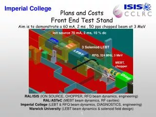
LEBT • Acceleration and beam matching to RFQ and safety • 50 kV electrostatic acceleration • 2 solenoid lens provide matching to the RFQ. • Beam stop system for personnel safety (to be added) • Decision: Adapt an old Fermilab Dualplasmatron system • Available in Y05 • Substantial cost saving • Refurbished in MS6 by the TD • HV testing of the existing electrodes is complete • Beam transport tests using a Dualplasmatron (H+) ~ May/June 06
H- Ion Source Requirements • LEBT beam parameters modified from RFQ input parameters • Beam current increased to account for losses in RFQ • Pulse length increased to account for chopping • Ion source investigation and collaboration started in 2004 • SNS and DESY RF multicusp ion source • FNAL and BNL magnetron ion source
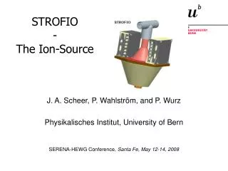
Modern H- Ion Source options? SNS H- source DESY H- Source
DESY RF Multicusp Volume Source • low duty factor (0.05-0.1%) • External antenna (2MHz) • Ignition: cold cathode in gas injection line • No cesium • Being adopted for SPL at CERN which is setting the stage for technology transfer • CERN cost estimate is aprox. 450 k$ Figure provide by Jens Peters, DESY
DESY RF Ion Source Testing DESY site visit Jan. 06 • Droop in beam current due to limit of RF and extractor power supplies • For higher duty factors heat loading would needs to studied • Emittance (RMS, norm.) for 40 mA is aprox. 0.25 π mm-mrad. Beam Current (10 mA and 500 μs / division), Forward and Reflected power ,operating at 0.5 Hz
SNS RF Ion Source Testing SNS site visit 2004 Informal collaboration established Red: Faraday cup Blue: Toroid with Droop correction 3.1 ms At 5 Hz • Tested 3.1 ms at 5 Hz and 65 KV extraction • Beam current average of 11-12 mA at 30 kW OF 2 MHz RF • Limited by average heat load of the primary RF amplifier • RF supply manufacturer indicated that this could easily be overcome • An RF power ramp should also help compensate for the 1-2 mA droop in the pulse.
Run # 9 BCM: 2A / V FC: 25 ohm 0.5 V / div SNS Ion Source Development (A) (B) • (A) Investigation of a hollow anode gas injection to provide extra electrons to the plasma • Short pulse, no cesium • (B) Operation is still being optimized • 16 days with an average beam current of 33 mA and a 0.5 mA/day beam attenuation rate. 85 million pulses (1.2 ms, 60 Hz) only 5 trip Data from Robert Welton, Fermilab Seminar, January 19, 2006
H- Ion Source for HINS in Meson • Magnetron ion source selected based on time, availability, cost and expertise!! • This buys us time! • Other labs continue to push the RF multicusp source and are willing to let us participate and learn. BNL source FNAL source
Magnetron Tests at BNL • (left) BNL site visit Feb. 06 • Peak at 1.1 ms is artificial (LEBT solenoids turning off). • Droop associated with PS • Test was to short to understand thermal effects (10 min. at 6 Hz) 20 mA / 200 μs per division. • (right) BNL Mark III 1975: • Multi-slit magnetron 350 mA!!! • 2.5 ms pulse, 0.1 Hz and 15 kV • K. Prelec and Th. Sluyters, PAC 1975, pg 1662. typically 120 A total current
Magnetron Emittance? Emittance Trend:No attempt to normalize or separate out cathode, aperture or LEBT/pre-accelerator types. The green line is a linear fit to the data and the pink curve represents a square root fit to the data. These emittance values were gleaned from the following reference: Schmidt, PNNIB, p.123 (1977) Alessi, PNNIB, AIP Conf. Proc. 158, 419 (1986) Stipp, IEEE TNS, 30, 2743 (1983) Smith, RSI 53, 405 (1982) Alessi talk associated with, AIP Conf. Proc. 642, 279 (2002) Criegee, Peters et al., RSI 62, 867 (1991) Schmidt, PNNIB, AIP Conf. Proc. 158, 425 (1986) Moehs, IEEE TPS, 33, 1786 (2005) Peters RSI 71, 1073 (2000) Welton, PNNIB, AIP Conf. Proc. 639, 160 (2002)
Emittance Evolution in the BNL LEBT H- beam from the BNL circular aperture magnetron. After about 75 μs the emittance profile is more or less stable. 10 μs 20 μs 30 μs 40 μs 50 μs 75 μs 100 μs 400 μs 500 μs Graphs provided by Jim Allessi, BNL
Ion Source Testing and Construction • Develop straight ahead variant on AD ion source test bench ~May-July 06 • Measure beam current • Optimize anode aperture size • Measure emittance • Optimize magnetic field • Test permanent magnet configuration • Possible delay: ARC and Extraction PS from EE support • H- source installation in MS6 ~ Aug. 06 • Design ion source mounting and extraction electrodes for LEBT • Measure beam current and transverse emittance • Possible delay in the future: emittance at 45 mA is not low enough • Move completed system to Meson ~ Fall 06 • Installation and connection to EPICs control system
Cost Estimates: Ion Source and LEBT • Y06 primarily in manpower • Part modification and refurbishment • Manufacture new Magnetron ion source components • Infrastructure installation at Meson • Y07 large items • Redundant beam stop system for personnel safety • SNS style emittance probes electronics and software
Conclusions • H- Source: Our plan provides for a reliable ion source for the HINS test facility in Meson while allowing time for RF multicusp source advances which might make this source type a better choice for the HINS in the long term. • RFQ: Using an RFQ for the initial acceleration stage of the HINS is common practice and commercial manufacturing is routine.