Download
1 / 28
310 likes | 542 Views
NSLS-II Beam Position Monitor System. Om Singh Instrumentation Group Leader ASAC Review - October 22-23, 2009. Outline. Injector RF BPM Button Storage Ring RF BPM Button RF BPM Electronics Photon BPM. Injector RF BPM buttons. Resolution Requirement High charge (15nC) 30 microns

E N D
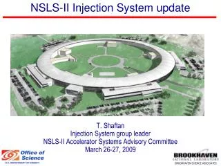
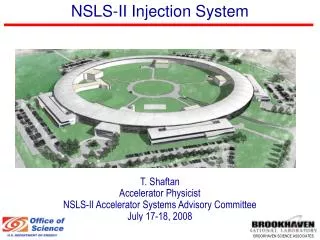
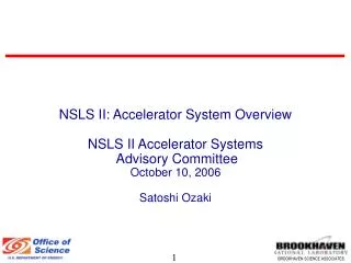
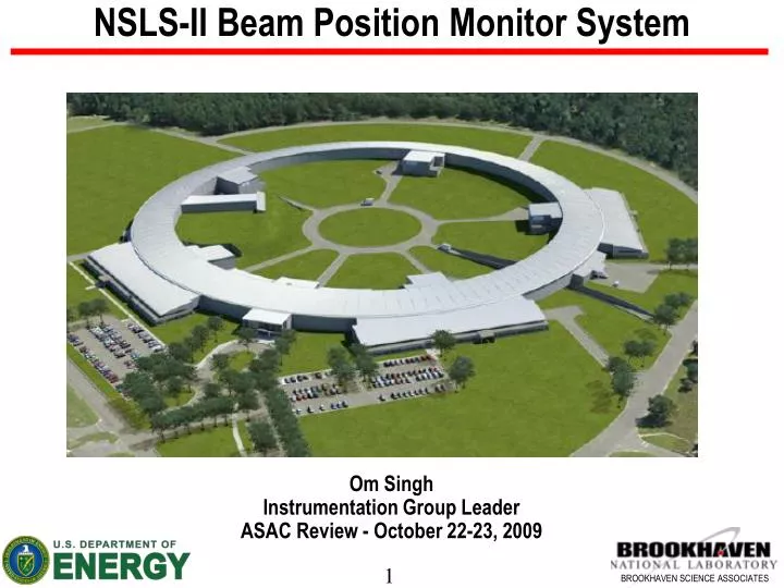
NSLS-II Beam Position Monitor System Om Singh Instrumentation Group Leader ASAC Review - October 22-23, 2009
Outline Injector RF BPM Button Storage Ring RF BPM Button RF BPM Electronics Photon BPM
Injector RF BPM buttons • Resolution Requirement • High charge (15nC) 30 microns • Low charge (0.05 nC) 300 microns • Simulation shows15 mm diameter buttons • will meet resolution requirement • BPM electronics - commercial or in-house Pinayev Padrazo * Multi-bunch mode with 0.1 nC per bunch; = 15 ps; Cb = 2.5 pF 4
Injector RF BPM buttons - continued • Sensitivity and power level calculations completed • 15 mm dia RF buttons assembly design in progress • Completion schedule – 1st Article 6/2010; Production 6/2011 Pinayev Padrazo Kosciuk 40x90 mm LTB beampipe 40x40 mm LTB beampipe
SR RF BPMs Location in a Cell 2 1 2 3 1 3 4 6 5
RF Cable Junction Box – SR Tunnel • Junction box – to interconnect • and to house passive components • SiO2 cables used @ buttons • LMR-240 used from box to rack DellaPenna Kosciuk
SR RF BPM Button Design – Trapped Mode Optimization NSLS-II button geometry 7 mm dia; 16mm hor sep Bunch Gaussian BW (=15psec) Freq of trapped mode (r=3.5mm) Relative voltage induced I. Pinayev, A. Blednykh, P. Cameron, B. Bacha
SR RF BPM Button Design – Heating Optimization FEA Thermal Simulation 1st Article Unit Kosciuk Cameron
SR RF BPM Buttons Procurement Status • Acquisition Status for large aperture (BLA) buttons (7mm dia) • First articles received and acceptance tests completed August 09 • Contract for 460 pieces awarded Sep 2009 • Production schedule Dec 2009 – June 2010 • Acquisition Status for small aperture (BSA) buttons (4mm dia) • Engineering drawing, Specification, and SOW complete – Mar 2010 • Contract Awarded - Apr 2010; Receive first articles – Jul 2010 • Acceptance testing, go-ahead to vendor for production – Sep 2010 • Order complete – Dec 2010 P. Cameron
Resonance Modes in Multipole Chamber (3.05m) Resonance modes can reside inside or too close to BPM pass band frequency – not good Measurement Set-up Blednykh Hseuh Ferreira Bacha 440 640 BPM Frequency Pass Band 492 – 508 MHz Resonance Modes could effect BPM performance and requires to be suppressed or moved out of BPM band RF Shields RF Shields • Use RF shield installed with modified NEG carriers in the ante-chamber • Shield located 147 mm from beam center – away from SR • Shield 500 mm long with 300 mm spacing – shifts Fo to > 530 MHz • Working on robust installation scheme – Review committee - 9/25/2009
RF BPM ELECTRONICS • 2/2009 – Completed evaluation of Libera, Bergoz and APS BPM electronics. Libera meets NSLS-II baseline technical requirements • 4/2009 - Shifted to evaluate other requirements - exposed several issues • Utilizes ~10 year old Virtex-2 FPGA technology - Virtex-6 is current • Insufficient capability for future application software – No room to grow • Cumbersome to manage future upgrades – FPGA source not given to NSLS-II • Limited Itech support for a quick response at Brookhaven – Located in Slovenia • AFE Crossbar switching improves drift compensation, but adds complications for TBT and fast orbit feedback data. • Expensive - $13,500 each (NSLS-II qty – 250) • 6/2009 – Attended Libera User Workshop at ESRF – mixed responses • 7/2009 – Motivated to evaluate an in-house BPM development & production • 10/2009 – Planning & design in advanced stage • 12/2009 – Make or buy decision finalized
NSLS-II RF BPM In-house Design Plan – 7/2009 • Challenges • Aggressive schedule • SR Stability Requirements • SR Resolution Requirements • Objective • Design and build in-house RF BPM’s for the Injection system and Storage Ring • Development Approach • Multi-phase development • Parallel development of AFE and DFE • System Integration Testing and Analysis • Beam Test • Iterate for performance optimization • Dedicated Lab • BPM Development Team • K. Vetter – • A. DellaPenna • J. DeLong • K. Ha • Y. Hu • B. Kosciuk • J. Mead – BNL Instrumentation • S. Orban • I. Pinayev • Y. Tian
RF BPM Prototype - Physical Architecture (7/2009) High Speed, Impedance Controlled Differential Connector (LVDS) FOFB A BPF ADC Fixed Point DSP + Cal Raw Data Control Interface First Turn T-B-T (10KHz) B BPF ADC Post Mortem Slow Data & Control Raw Data C BPF ADC Slow Acquisition Timing InterLock InterLock D BPF ADC Virtex-5 Calibration ADC Clock Memory DDR2 SDRAM AFE DFE AFE - Under Sampling (initial proposed concept) - Factory Calibration (gain, temperature) - Dynamic Calibration • DFE • - Fixed Point Digital Signal Processing, Position calculation, PU Linearization • - Embedded Eventlink • - Digitally Assisted AFE Calibration • Factory Calibration – Remove Systematic Errors • Dynamic Calibration – Remove Drift • - Communication Links
Spectrum with Calibration • Duplexer • Frequency multiplex RF Signal from pickup with continuous calibration tone. • Cal tone tracks RF Signal passband Insertion Loss by virtue of Monolithic Distributed design • Currently working with vendors to optimize filter response, cost, and complexity • Bessel/Gaussian 5th-order Transitional filter (e.g Gaussian to -3/-6dB, Chebychev) under investigation for RF Signal passband • Bessel, Butterworth and Chebychev response under investigation for Pilot-Tone passband RF Duplexer Theoretical Response Target Rejection = 60dB Cal Tone Passband RF Signal Passband K. Vetter
Calibration Concept #1 - (Out-of-Band Pilot Tone via RF Duplexer) In-Tunnel hardware • Benefits • Continuous Real-Time Calibration • No perturbations to signal path • Inherent Built-In Test K. Vetter 0.0007dB Gain Balance Required for 200nm offset @ k=10mm
RF BPM Prototype Development Plan (7/2009) AFE DFE Beam Test
RF BPM Development Status – 10/2009 • Started RF BPM development – July 2009 • RF BPM architecture in mature stage (next slide) • DFE Board Schematic 90% complete. Board layout to begin this month • 1-month ahead of schedule • Developing Requirements for custom RF Duplexer - Complete in November 2009 • ADC Evaluation started. Evaluating performance of four Candidate ADCs • RF BPM Thermal Analysis started • Highly desirable to have passive cooling (no fans) • Take advantage of the temperature control rack capable of ±0.1°C stability • Establish convective heat transfer coefficient inside the rack via accurate FEA study. • With accurate boundary conditions and preliminary board layout, predict operating temperatures of FPGA and other electronic components. • Start AFE layout in December 2009 • Preliminary chassis layout in advance stage – more later • Power supply requirements 85% complete • RF BPM Development space – Lab acquired; Test equipment procurement in progress K. Vetter
NSLS-II RF BPM Architecture – 10/2009 • Bandpass Sampling • 16b ADCs • Sample Rate ~ 113MHz • Xilinx Virtex-5 • FOFB @ 10KHz • SA @ 10Hz • Embedded PC with Linux OS • Embedded Floating-Pt coprocessor • Embedded EventLink • 128Mbyte DDR2 • Active Calibration for long-term drift • Factory Calibration to remove systematic errors • DFE platform adaptable to other NSLS-2 applications
NSLS-II BPM Mechanical Concept DFE AFE Modular Approach - separate AFE, DFE RF SMA Connectors Triggers Kosciuk Orban Tian SFP Communication Ports Same chassis as Power Supply Interface (PSI), PS Regulator Module, and Cell Controller
X-BPM Concept Photo Emission Type XBPM assembly B. Kosciuk P. Ilinski Translation stages Invar based High stability stand
Typical Front End Configuration – XBPMs Shown Ratchet Wall Collimator Dual Safety Shutters Shrama Doom Fast Gate Valve Photon Shutter XBPM 1 Lead Shield XBPM 2 Fixed Aperture Mask Safety Shutter Collimator Slow Gate Valve Bending Magnet photon shutter Ion Pump X-Y Slits Ion Pump with TSP Ion Pumps with TSPs Collimator
SUMMARY • Injector RF button design in progress. Button delivery on schedule • SR RF buttons – • Design completed including heating optimization • 1st article accepted successfully; Production delivery starts 12/2009 • Resonance modes solution in progress; SR shield review held; recommendations are being evaluated • NSLS-II RF BPM Electronics – • Evaluated BPM electronics • Libera meets technical requirements, but falls short in several other areas • In-house design study in progress; prototype test with beam 4/2010 • Installation schedule will be met with in-house BPM electronics
Acknowledgment B. Bacha, A. Blednykh, A. Borrelli, P. Cameron, W. Cheng, L.B. Dalesio, J. De Long, P. Ilinski, A.J. Della Penna, L. Doom, M. Ferreira, G. Ganetis, W. Guo, H-C Hseuh, E.D. Johnson, B.N. Kosciuk, S.L. Kramer, S. Krinsky, F. Lincoln, C. Longo, W. Louie, J. Mead, S. Orban, D. Padrazo, I. Pinayev, J. Ricciardelli, G. Shen, S. Sharma, J. Skaritka, C. Spataro, T. Tanabe, Y. Tian, K. Vetter, W. Wilds, F.J. Willeke, L-H Yu
Rogue Mode Requirements - (From RF BPM Perspective) K. Vetter
Acceptance Testing of the 5 First Article Buttons • Dimensional verification and leak checking done at the vendor’s facility. • The following acceptance testing completed at BNL • Vacuum Group - leak check, bake, leak check – <2*10-10 std.cc/sec • Central Shops - dimensions verified using CMM (coordinate measuring machine) • Diagnostics Group • Capacitance – ~4pF, divided evenly between button and feedthru (one assembly shipped without buttons to permit this measurement) • Contact insertion and withdrawal force • Leakage resistance and voltage holdoff • VSWR • Trapped mode frequency (avoid the RF harmonics) and Q • Thermal response to button heating • In addition, Central Shops sectioned one assembly (wire EDM) to permit inspection of internal construction details.
Button Assembly 001, and Test Fixtures Bacha Cameron Kosciuk trapped mode frequency measurement SMA contact insertion force measurement