Download
1 / 27
270 likes | 376 Views
NSLS-II Injection System. T. Shaftan Accelerator Physicist NSLS-II Accelerator Systems Advisory Committee July 17-18, 2008. Acknowledgements. R. Heese, J. Rose, N. Tsoupas, I. Pinayev, S. Ozaki, F. Willeke, E. Weihreter, Y. Li, W. Guo, B. Nash,

E N D
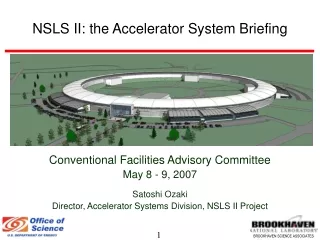
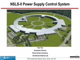
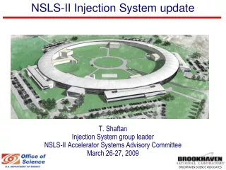
NSLS-II Injection System T. Shaftan Accelerator Physicist NSLS-II Accelerator Systems Advisory Committee July 17-18, 2008 NSLS-II Accelerator Systems Advisory Committee, July 17-18, 2008
Acknowledgements R. Heese, J. Rose, N. Tsoupas, I. Pinayev, S. Ozaki, F. Willeke, E. Weihreter, Y. Li, W. Guo, B. Nash, M. Fallier, M. Ferreira, R. Alforque, S. Krinsky, E. Johnson, A. Blednykh, O. Dyling, R. Meier, S. Sharma, D. Hseuh, G. Ganetis, T. Shaftan, O. Singh, J. Skaritka, M. Rehak, J. O’Connor, C. Lavelle, P.K. Job, B. Casey, T. Mennona NSLS-II Accelerator Systems Advisory Committee, July 17-18, 2008
Outline • Introduction • Injector design specifications and main parameters • Injector layout • Linac • Booster • Transport lines • Storage Ring injection straight section • Summary • Future plans NSLS-II Accelerator Systems Advisory Committee, July 17-18, 2008
Introduction • NSLS-II requires reliable injector capable of filling and maintaining storage ring current • Top-off mode of injection is required • More detailed design has been developed on preliminary design of 200 MeV linac and 158 m 3 GeV booster presented at the ASAC in Oct. 2008 • Linac and booster are envisioned as semi-turnkey procurements • Transport lines and ring injection straight are going to be built by BNL NSLS-II Accelerator Systems Advisory Committee, July 17-18, 2008
Storage Ring Parameters Related to Injection NSLS-II Accelerator Systems Advisory Committee, July 17-18, 2008
Requirements for NSLS-II Injection Iinj 1min I t 1/5 4/5 I t NSLS-II top-off format t • Discussed with users on their desired bunch patterns and top-off formats • Two bunch patterns are in NSLS-II baseline: • 4 or 5 bunch trains with shorter gaps totaling about 80% of the full buckets • uniform fill with 20% ion-clearing gap • Complex bunch patterns (camshaft bunches or 100% uniform fill) are not precluded and foreseen as future upgrades. Current stability and purity • Relative current stability of 1% is the baseline number. • Charge in empty bucket <10-4 x nominal charge • Minimum interval between two consecutive top-off is 1 min. • Gating signal to users is to be provided. NSLS-II bunch patterns 1 turn NSLS-II Accelerator Systems Advisory Committee, July 17-18, 2008
Top-Off Injection Scenario Injected bunch train (NM=80-150) Ib t Ring bunch pattern # • Many (~1000) bunches in the ring multi-bunch injection • NM bunches in the injected train • Filling NM consecutive buckets in the ring • Sequentially shift the injection timing • 1 Hz injector rep rate suffices with pulse train injection • 1 minute between injector cycles for top-off • Interacting with users on the requirements for top-off and complex bunch patterns • Developed simulation on SR pattern non-uniformity • Evaluated rate of contamination of “empty” buckets by Touschek-scattered particles 80 bunches in injected train 150 bunches in injected train NSLS-II Accelerator Systems Advisory Committee, July 17-18, 2008
NSLS-II Injector Complex Overview Injection straight B-SR TL 3-GeV booster 200-MeV linac NSLS-II Accelerator Systems Advisory Committee, July 17-18, 2008 LB TL
Linac SOLEIL linac • SR injection: 7.3 nC/min 10% loss at SR injection 20% loss at booster extraction 30% beam loss at booster injection 15 nC per pulse • NSLS-II: 200 MeV, 15 nC/train, ~0.5% energy spread • Linac can be procured turn-key • January 2008 we visited SOLEIL and THALES • Acquired information regarding linac hardware, utilities and performance • Acquired information on beam measurement data • Participated in linac studies SOLEIL measurement of injected bunch train J. Rose NSLS-II Accelerator Systems Advisory Committee, July 17-18, 2008
Linac Configuration Thales linac J. Rose, R. Meier • 3 GHz, 100 MeV linac is in operations at ASP (ACCEL) • 3 GHz, 100 MeV linac is in operations at SOLEIL (THALES) • Achieved parameters: • 4/0.25 nC/pulse in LPM/SPM at ASP • 10/0.5 nC/pulse in LPM/SPM at SOLEIL • Close to NSLS-II requirements • Linac Front-End funding is planned in FY09 to procure and establish gun performance NSLS-II Accelerator Systems Advisory Committee, July 17-18, 2008
Booster Lattice • Booster accelerates beam from 200 MeV 3 GeV • Tracking studies have been carried out with nearly complete ring model: booster emittance of ~30 nm is adequate for low-loss injection • Compact (158.4 m) and low-emittance (30 nm at 3 GeV) lattice • Accelerates bunch trains • Repetition rate of 1 Hz • Charge per train 10 nC • RF system (by BNL): PETRA cavity and IOT • Optimized injection and extraction systems: DC septa • Semi turn-key procurement that is close to existing solution Structure Acknowledge work of W. Guo, Y. Li, B. Nash NSLS-II Accelerator Systems Advisory Committee, July 17-18, 2008 Similar to Australian Synchrotron Project booster
Progress on booster lattice Dynamic aperture Dipole physical aperture Y. Li • CD2 New lattice version • Similar magnet parameters as in CD2 lattice • Straight section length increased 7.05 7.7 m • Vertical tune (and chromaticity) is decreased • DA (on- and off-energy) is increased to larger than vacuum chamber aperture • Dispersion in straight decreased to 10 cm • Emittance is 33 nm at 3 GeV – needs more work • Orbit correction scheme is adequate • 20 mA in the booster: study of collective effects is under way NSLS-II Accelerator Systems Advisory Committee, July 17-18, 2008
Optimization of booster extraction and injection systems pulsed septum DC septum pulsed septum B B B B B B B B kicker kicker QG QG QF QG QF QF QG QF • CD-2 • A single pulsed septum 150 mrad • Assume beam divergence of 80 urad (horizontal) at extraction • RMS beam divergence = error at: • Kicker stability (flatness) of 1.6% • Septum stability (flatness) of 0.05% • Reducing sensitivity to waveform jitter and noise • CD-3 • Combination of weak pulsed septum (47 mrad) and DC septum (96 mrad) • Kicker stability (flatness) of 1.6% • Septum stability (flatness) of 0.2% NSLS-II Accelerator Systems Advisory Committee, July 17-18, 2008
Magnet design DC extraction septum • Magnet definition is in progress for injector: • LB TL: 4 dipoles, 14 quadrupoles • Booster injection and extraction system • BSR TL: 4 dipoles, 16 quadrupoles • Injection straight: pulsed magnets • Transport lines: • Quadrupoles: 2 type of yokes, 3 types of different coils • Dipoles: 3 types of yokes, 3 types of coils • Correctors: 2 types of yokes, 2 types of coils • Complex magnets: DC extraction and SR injection septa • Soon start magnetic design of pulsed magnets Transport line quadrupole M. Rehak, R. Heese NSLS-II Accelerator Systems Advisory Committee, July 17-18, 2008
Layout of LB TL ES In the past months: • SOLEIL experience: energy slit after linac is very helpful • Redesigning LB TL to increase dispersion at energy slit • New booster injection scheme is implemented • Beam optics is complete • Local shielding design is under way • Diagnostics beam lines are to be designed R. Heese, R. Meier NSLS-II Accelerator Systems Advisory Committee, July 17-18, 2008
In the past months: • Addressed all incompatibility between TL and building • New booster extraction scheme is implemented in the BSR TL • Beam optics complete • Placement of corrector magnets, and beam diagnostic devices complete • Tolerance studies complete • Diagnostics beam line is being designed N. Tsoupas, R. Meier Booster to Storage Ring Transport Line NSLS-II Accelerator Systems Advisory Committee, July 17-18, 2008
Storage ring injection straight • Quad-to-quad distance is 9.3 m • Combination of strong DC pre-septum with pulsed septum • Closed bump of 15 mm • Kickers with 5.2 μs long pulse powered separately • Pulsed magnets (3.15 GeV max) are within vendors capabilities • Magnet and PS design is under way • Development and optimization of pulsed magnets and PS (total of 13 magnets of 7 types for NSLS-II) in-house: Pulsed Magnet Lab in FY09 R. Heese, M. Ferreira, D. Hseuh NSLS-II Accelerator Systems Advisory Committee, July 17-18, 2008
Pulsed magnet tolerance analysis Horizontal error scaling for kicker mismatch • Study of the residual field errors in closed bump (for the maximum stored beam displacement) • Vertical error: random kicker roll of 0.5 mrad (3.75 µrad angular vertical kick) • Horizontal error: 0.1% kicker-to-kicker random amplitude mismatch • Consider combination of 4 kickers and scale total to the Source Points of Short and Long Straight sections • Compare with RMS beam size and divergence at the Source Points • Horizontal error is of order of RMS beam parameters • Vertical error exceeds RMS parameters • Need set-up of Pulsed Magnet Lab to develop methods of error reduction • Tolerance analysis is ongoing Orbit angle at SP (µrad) Orbit shift at SP (µm) Vertical error scaling for residual kicker roll Orbit angle at SP (µrad) Orbit shift at SP (µm) NSLS-II Accelerator Systems Advisory Committee, July 17-18, 2008
Injector building 18 17 16 15 14 13 12 Supplemental shielding 11 Penetration N Safety device 10 Cabling 1 2 Entrance 3 4 5 6 7 9 8 NSLS-II Accelerator Systems Advisory Committee, July 17-18, 2008
Utilities, injector components, safety • Multiple iterations on building layout • 80% Title II Design complete • Injector utilities (electric power, water, compressed gas) are specified • Injector components • Booster Power Supplies performance specs established • Injector element specification is in progress • Injector magnet design and PS specs are in progress • Cable/signal list is compiled • Component naming convention to be discussed • Safety review took place • Assessed beam parameters envelope • Assessed beam confinement system • Design of safety devices is under way APS safety shutter NSLS-II beam dump design R. Alforque NSLS-II Accelerator Systems Advisory Committee, July 17-18, 2008
Procurements • Linac: visited THALES and SOLEIL in January • Linac Front-End to be procured in FY09 • Booster RF: visited DESY in July • Booster: two potential vendors visited NSLS-II in January and March • Booster Statement of Work completed in April • Information on: • Scope of delivery • Timeline • Performance specifications • Acceptance testing • Conventional constructions • Mechanical and Electrical utilities • Diagnostics and Controls • Norms and Standards • Booster SOW was sent to three potential vendors for budgetary quotes and schedules • Expecting information from two vendors in August NSLS-II Accelerator Systems Advisory Committee, July 17-18, 2008
Summary • NSLS-II full energy injector will support top-off operations in presence of limited beam lifetime • Multi-bunch injection with high charge per bunch train • Linac and booster are envisioned as major procurements • NSLS-II booster is based on existing design (low-emittance cost-effective solution) with modifications • We are moving forward with design of injection straight section and transport lines • In the design process we use experience from other state-of-art light sources • In the past months injector development was focused on: • Finalizing injector building specifications • Setting specifications on utilities, safety systems, interfaces with NSLS-II subsystems • Optimization of the booster lattice, injection/extraction systems • Transport line design and specification of components • Design of the storage ring injection straight • Interaction with vendors • Draft of CD-3 Design Report is nearly ready NSLS-II Accelerator Systems Advisory Committee, July 17-18, 2008
Important dates for NSLS-II injector • CD-2: injection system baseline design is developed • During FY08-FY09 we are refining design and perform value engineering effort, prepare specs for procurements • Specifications are ready for procurement: • Linac Oct 09 • Booster Aug 09 • Booster RF Aug 11 • Utilities Dec 10 • TL Mar 10 • At this point the design and specs by BNL are finalized • Procurement begins: • Linac Oct 10 • Booster Mar 10 • TL Apr 10 • Utilities Nov 09 • Injector Building BOD end Nov 11 NSLS-II Accelerator Systems Advisory Committee, July 17-18, 2008
Extra NSLS-II Accelerator Systems Advisory Committee, July 17-18, 2008
Uniformity of bunch pattern • Requirement on SR bunch pattern uniformity is 20% • Can we preserve the uniformity while executing top-off with bunch trains? • “Hunt&Peck” mode of injection at SLS • Simulation with assumptions: • Touschek-limited lifetime • Phase transient induced by harmonic cavity • Noisy (20%) injected bunch train • Filling consecutive N=80…150 buckets in one top-off cycle • Results after 2 days of continuous top-off show no deterioration of bunch pattern • “Hunt&Peck” mode with bunch trains to be studied 80 bunches in injected train 150 bunches in injected train NSLS-II Accelerator Systems Advisory Committee, July 17-18, 2008
Maintaining purity of “empty” RF buckets • To maintain the purity of empty buckets on 1E-4 level we will need to do cleaning ~every 3 min • Very first energy band is located at 4.3% off the nominal energy. • This is a pessimistic estimate assuming no limits on machine energy acceptance. Real energy acceptance (limited by a scraper) will reduce migration rate. • This analysis includes only Touschek-scattered particles migrating from full to empty buckets. In reality there will be additional particles coming from injected beam every top-off cycle. • Needs an analysis of the bunch cleaner in the booster. NSLS-II Accelerator Systems Advisory Committee, July 17-18, 2008
Booster RF System • Signed MOU with DESY for two 5-cell PETRA cavities, to be delivered in early FY2009 • Need to work out coupler interface NSLS-II Accelerator Systems Advisory Committee, July 17-18, 2008