Download
1 / 25
270 likes | 456 Views
NSLS-II Injection System update. T. Shaftan Injection System group leader NSLS-II Accelerator Systems Advisory Committee March 26-27, 2009. Acknowledgements. R. Heese, J. Rose, R. Fliller, B. Parker, M. Rehak, S. Ozaki, F. Willeke, E. Weihreter, Y. Li, S. Kramer,

E N D
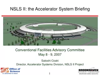
NSLS-II Injection System update T. Shaftan Injection System group leader NSLS-II Accelerator Systems Advisory Committee March 26-27, 2009 NSLS-II Accelerator Systems Advisory Committee, July 17-18, 2008
Acknowledgements R. Heese, J. Rose, R. Fliller, B. Parker, M. Rehak, S. Ozaki, F. Willeke, E. Weihreter, Y. Li, S. Kramer, W. Guo, B. Nash, M. Fallier, M. Ferreira, R. Alforque, S. Krinsky, E. Johnson, A. Blednykh, O. Dyling, R. Meier, S. Sharma, D. Hseuh, G. Ganetis, H. Ma, T. Shaftan, O. Singh, J. Skaritka, N. Tsoupas, J. O’Connor, C. Lavelle, I. Pinayev, E. Trakhtenberg, P.K. Job, B. Casey, T. Mennona, G. Woods, J. Zipper NSLS-II Accelerator Systems Advisory Committee, March 26-27, 2009
Outline • Injector design specifications and requirements • Linac • Booster • Transport lines • Storage Ring injection straight section • Pulsed Magnet lab • Summary NSLS-II Accelerator Systems Advisory Committee, March 26-27, 2009
Introduction-Requirements • NSLS-II requires a reliable injector capable of filling and maintaining storage ring current • Top-off mode of injection is required • Specifications for NSLS-II injector • Storage ring: 3 GeV, 0.5 A, 1080 bunches in 1320 RF buckets, 3 hr lifetime • Top-off: deliver 80…150 bunches with 7.3 nC total charge once a minute total stability of ring current 0.55%, bunch-to-bunch charge deviation 20% • Repetition rate of 1 Hz is sufficient with multibunch injection: Initial fill 00.5 A in 3 min • Supported Storage Ring Bunch patterns: • Baseline: uniform fill with 20% ion-clearing gap or 4-5 bunch trains with short gaps • Future upgrade: camshaft bunch(es), uniform fill • Future upgrade: Bunch cleaning, Empty/Full RF bucket charge ratio 0.01% • Last year’s work: analysis of ring bunch pattern uniformity and calculation of contamination of empty ring buckets • Dialog with NSLS-II users on injection requirements
NSLS-II Injector R. Meier NSLS-II Accelerator Systems Advisory Committee, July 17-18, 2008
Injector building 18 17 16 15 14 13 • Multiple iterations on building layout: no conflicts with injector • 100% Title II Design complete • Injector utilities (electric power, water, compressed gas) are specified • Injector BOD is moved up in schedule to May 2011 • Construction starts soon! 12 Supplemental shielding 11 Penetration N Safety device 10 Cabling 1 2 Entrance 3 4 5 6 7 9 8 NSLS-II Accelerator Systems Advisory Committee, July 17-18, 2008
Linac Linac FE An option • Design and Modeling • THALES linac model is in studies; charge/ bunch scaled up • Linac Front-End beam dynamics completed • Linac Front-End diagnostics station design is assessed • Overall linac design is nearly complete • Next steps: • Set-points and tolerances • Initial conditions for transport line • Diagnostics performance R. Fliller J. Rose 90 keV R. Fliller 15 MeV NSLS-II Accelerator Systems Advisory Committee, March 26-27, 2009
Booster Y X • Tests of injection efficiency • Injection modeling with CD2 booster lattice at injection energy • “Square” magnet model • Magnet errors • Misalignments • RF cavity • Orbit/Tune correction • Conclusions: • SC aperture of CD2 lattice (X:15mm/1.7mrad; Y: 5.6mm/1.4mrad) • Substantially smaller than that in ASP • Tighter tolerance for injection errors • Prohibits concept of beam stacking considered before • “4-bump” concept of beam stacking is under consideration R. Fliller NSLS-II Accelerator Systems Advisory Committee, March 26-27, 2009
Booster CD-2 • Finalizing preliminary lattice design • CD-2 lattice • High y High y • Small footprint of large DA in tune space • High sensitivity to errors • Small stay-clear aperture • Straight-section length 7.05m • Strong quadrupole • High dispersion in straights • Long BD magnets (3.6 GeV) • Several new lattice versions have been developed new S. Kramer, R. Fliller NSLS-II Accelerator Systems Advisory Committee, July 17-18, 2008
Booster M. Rehak • Booster magnetic element analysis • Models of all dipoles, quadrupoles, sextupoles, correctors are created • Coil models developed • R, L, UPS, IPS, P are calculated • Compared with the ASP values • “Build-in-house” booster cost estimate • Cost/labor of subsystems (accelerator design, magnets, PS, vacuum, controls, instrumentation/ diagnostics) were estimated • Compared with vendors’ cost estimates • Work on preparation of procurement documents is ongoing • Booster RF cavities arrived and being tested(see J. Rose’s talk) OPERA-3D MERMAID Analytic estimate NSLS-II Accelerator Systems Advisory Committee, March 26-27, 2009
Extraction system design • Extraction septum design • Geometry of extraction straight: DC septum is close to booster chamber • Septum design (shielding) leads to field of only ~1Gs inside booster chamber • Ramping DC septum is a possibility • Extraction magnet tolerances • Booster emittance is small (~35 nm) • Tolerances (<20% of x): • extraction kicker -- 0.2% amplitude • extraction septum – 0.02% amplitude Extraction septum: B. Parker NSLS-II Accelerator Systems Advisory Committee, March 26-27, 2009
Transport lines • Optimization of TL elements • Revision of instrumentation • Consideration of commissioning scenario NSLS-II Accelerator Systems Advisory Committee, March 26-27, 2009
Kicker tolerances in 4-kicker bump RMS beam size 1st SS orbit angle • Tolerance analysis focusing on: • Tilt of kickers • Kicker amplitude mismatch • Calculations cross-checked via • Analytic calculation • Tracking particles in complete SR model • Assuming realistic waveforms and multiple turns • Observing orbit shift and angle in source points (centers of straight sections) • Conclusions: to maintain x,x’ <0.1x,x’ • Kicker amplitude mismatch A< 0.810-4 • Kicker roll y<1.2 10-5 rad • Discussing tolerances with users • Developing Pulsed Magnet lab 2nd SS 3rd SS orbit shift NSLS-II Accelerator Systems Advisory Committee, March 26-27, 2009
Storage ring injection straight section Lk xk septum xs PSM L F. Willeke 1 • We are considering injection via pulsed multipole magnet • Both quadrupole and sextupole schemes were analyzed; sextupole is chosen • Geometry layout with PSM is developed • Guidelines for PSM design: • Angle/coordinate at injection point are same as for baseline (4k) scheme • Same (or close) angle/coordinate at entrance of injection straight section • Same requirements on DA of storage ring for injection • Waveform 2 revolutions (5.2 µs) long 3 2 Normalized phase space 3 2 1 NSLS-II Accelerator Systems Advisory Committee, March 26-27, 2009
Pulsed Sextupole magnet PSM optimization: M. Rehak 50 µH 30.75 µH 14 µH • Pulsed Sextupole magnet design • 0.5 m long, field 0.5 T pole tip, half-sine pulse 5.2 µs long • Design goal: minimize inductance and, thus, PS voltage • Current magnet layout is close to the that of PF in Japan (H. Takaki et al., PAC-2007) • PS voltage 30 kV, current 3 kA • OPERA 3D with time dependence • PSM tolerances • Considered PSM transverse translations and tilt • Conditions x,x’ <0.1x,x’ for stored beam orbit • Conclusion: vertical alignment tolerance <10 µm! • Impact on stored beam size/shape • Insignificant Distortion of beam shape in horizontal phase space (PSM) no PSM PSM NSLS-II Accelerator Systems Advisory Committee, March 26-27, 2009
PSM: Summary R. Meier • Advantages • Replacing 4 pulsed magnets • Increasing reliability • Decreasing cost • Beam dumps less risky • Challenges • Tight tolerances on vertical alignment • PS (27 kV, 3.2 kA) • Tight arrangement of injection straight to maximize distance septum-PSM • PSM induces strong focusing for injected beam • Difficult to match BSR TL (large beam size) • BSR TL requires more magnets • This injection scheme requires high stability of both injected and stored beams • Conclusions: • Build prototype of PSM and PS in Pulsed Magnet lab • Work out feasible scheme for PSM alignment and trajectory controls PSM septum x=6mm R. Fliller y=1.5mm NSLS-II Accelerator Systems Advisory Committee, March 26-27, 2009
Pulsed Magnet Lab Status Bldg. 832 • Pulsed Magnet lab is being set up for • performance evaluation and calibration of final magnets • test innovations and concepts required to make top-off operation transparent to NSLS-II users • Tolerances required to have non-invasive top-off injection will be difficult to meet and maintain, some innovation is required • Present funding is inadequate, request for additional funding has been presented • PML status • Lab space assigned, materials/tools on order • 35 ft. x 15 ft. caged, interlocked test area under construction • Sr. Scientist on board full time • Experienced Head Technician hired • Post-Doc starting in mid-April • Engineering candidate in interview process • First order of business: Pulsed sextupole prototype construction and evaluation R. Heese
Summary • Injector design is on-going • Injector is entering procurement stage; expediting procurements of linac and booster • In the past few months work was focused on: • Setting injector specifications • Preparation of linac and booster procurements documents • Meeting with vendors • Designing injector magnets • Revising diagnostics for TLs and considering commissioning scenario • Developing injection scheme via Pulsed Sextupole magnet • Starting set up of Pulsed Magnet lab • Studying tolerances for pulsed magnets NSLS-II Accelerator Systems Advisory Committee, March 26-27, 2009
Extra NSLS-II Accelerator Systems Advisory Committee, July 17-18, 2008
Comparison 4K PSM PSM 4 Kickers Magnets Power Supplies R. Heese, E. Weihreter NSLS-II Accelerator Systems Advisory Committee, July 17-18, 2008
Response to the ASAC-2008 comments • Expedite injector procurements • Accelerated schedules for linac/booster are prepared • Procurement documents are getting ready • Funds may available for accelerated procurement • Injector building BOD is moved up by 6 months • Group tenders for linac and linac FE into one • Yes; early procurement for linac FE. See J. Rose’s talk. • Do not procure linac FE in advance • Need to test and commission LFE early to prove feasibility of the design • Need to test performance in flexible bunch pattern mode • still planning on procuring LFE in advance • Insufficient labor resources for pulsed magnets development • Actively hiring personnel, postdoc and tech is onboard • Looking for a skilled electrical engineer NSLS-II Accelerator Systems Advisory Committee, March 26-27, 2009
Response to the ASAC-2008 comments Cont’d • Including RF system into booster contract? • Under consideration • Analyze the Pulsed Sextupole option as the ring injection scheme • In progress; decision to be made in Dec. 2009 • Standard pumps and gauges across the project • Yes • High bunch purity implies special diagnostics/ cleaning system • Not included into the baseline scope • Will not be precluded by the current design; provisions for stripline and scraper are made (spool pieces) • Will be implemented as a future upgrade NSLS-II Accelerator Systems Advisory Committee, March 26-27, 2009
Important dates for NSLS-II injector • CD-2: injection system baseline design is developed • During FY08-FY09 we are refining design and perform value engineering effort, prepare specs for procurements • Specifications are ready for procurement: • Linac Oct 09 • Booster Aug 09 • Booster RF Aug 11 • Utilities Dec 10 • TL Mar 10 • At this point the design and specs by BNL are finalized • Procurement begins: • Linac Oct 10 • Booster Mar 10 • TL Apr 10 • Utilities Nov 09 • Injector Building BOD end Nov 11
Injection System Hardware Changes Since Baseline • Thick septum magnets have been replaced by special DC magnets • Pulsed septa for ring injection and booster extraction have been made as short as possible • Booster injection septum moved to upstream end of injection straight to adapt to more capable transport line Changes under investigation • Ring injection with pulsed sextupole magnet • Double Lambertson septum PSM for ring injection • Can septum magnets can be built similar to NSLS septum magnets
Where we are • Necessarily a snapshot of work in progress • Booster baseline injection and extraction systems with matched transport lines are designed (beware extraction kicker and extraction hardware stability) • Injection into Storage ring tricky due to stability requirements – injection transient restricted only to injection straight • Baseline injection system uses four kickers, injection septum, but with DC injection bender and pulsed Ht correction windings in bump magnets. • Six PUE’s will be installed - not necessarily instrumented at first. • Beam based correction and feed-forward on magnetic field pulses will ultimately be used. • Investigate different approach to septum construction, à la NSLS, with no current carrying feed-through into vacuum • Injection with pulsed sextupole appears feasible, measured magnet prototype due to be completed by December this year. • Possibility exists of using two Lambertson septa with PSM, resulting in only one pulsed component in the ring injection process (under investigation, geometrically it is feasible)