Download
1 / 28
280 likes | 294 Views
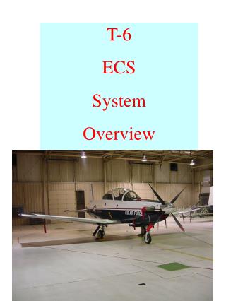
T-6B Environmental Control System (ECS). Created: 5 Sep 2015 Updated: 18 Sep 2015. Objectives. Identify components and understand operation of heating/defog/ventilation/air conditioning systems Understand Environmental Control Panel switches and operation

E N D
T-6B Environmental Control System (ECS) Created: 5 Sep 2015 Updated: 18 Sep 2015
Objectives • Identify components and understand operation of heating/defog/ventilation/air conditioning systems • Understand Environmental Control Panel switches and operation • Identify operations limits of heating/defog/ventilation/air conditioning systems • Identify canopy components and understand normal and emergency operations • Identify anti-G components and understand normal operations of system (Utilize ECS system schematic while reviewing this slideshow)
References • T-6B NATOPS Manual • Section 1 • Environmental Control System • Bleed Air Supply System • Canopy Seal and Anti-G System • Heating and Defogging System • Pressurization System • Cockpit and Avionics Cooling System • Fresh Air Ventilation • Canopy • Canopy Operation Procedures • Canopy Fracturing System (CFS) • Emergency Ground Egress System • Section 5 • Figure 5-1 Instrument Markings • Miscellaneous Limitations • Equipment Cooling Limitations • Cockpit Pressurization System Limitations • Canopy Wind Limitations
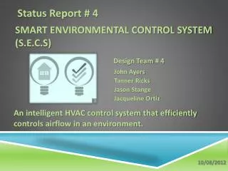
DEFOG RAM/DUMP RAM AIR FLOW BLEED AIR INFLOW CANOPY AUTO Rt Side P3 Port HI HI DEFOG (ON): -Opens BLFC & BPV -Opens BLFC & SOV to “HI” -Turns on Air Conditioner -Up to 40 sec to close Bleed Air Inflow: HI: Full open NORM: Half-way open OFF: Closed NORM COLD NORM DUMP HOT MANUAL OFF OFF OFF NORM FOOT Inflow Valve (Bi-Level Flow Control & Shutoff Valve) PRESSURIZATION Defog Valve (Bi-Level Flow Control & Bypass Valve) Cowl Vent Canopy Seal/Anti-G Electric Shutoff Valve Blower ECS System Overview Heat Exchanger WOW Fresh Air Valve Water Separator (Closes @ 8,000’) Heat Exchanger Bypass Valve • Provides automatic temperature and pressurization control • Utilizes engine bleed air from right side for heating, defog, pressurization, anti-G, and canopy seal • Cockpit cooling provided by a separate vapor-cycle system(air conditioning) • Fresh air ventilation available for non-pressurized flight • Environmental Control Panel in front cockpit only 60-90 F Firewall Shutoff Valve 7 psi Safety Valve Heating Sys Ejector (Increases defog volume) Temp Sensor Canopy Seal Valve Defog Defog Butterfly Valve Foot Warmer Evap Blwr DUCT TEMP 300 F Temp Sensor G-Suit CKPT ALT Cockpit Temp Control Sensor (Cabin: 19,000’) Acft AltCabin Alt 31,000’ 16,600’ 18,069’ 8,000’ (3.6 +/-0.2 ΔP) 8,000’ 8,000’ (Pressurization Begins) Butterfly Valve Defog Foot Warmer Evap Blwr G-Suit Cabin Temp Sensor WOW Dump Solenoid Control Valve Regulator Delta-P Regulator Safety Outflow Valve Control Valve (Delta-P: 3.6 +/-0.2) CKPT PX Pressurization: RAM/DUMP: Opens Control Valve & Fresh Air Valve / Dumps press DUMP: Dumps press NORM: Follows normal press sched (Delta P: 3.9 - 4.0)
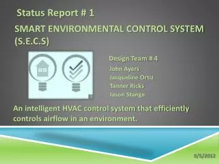
DEFOG BLEED AIR INFLOW Rt Side P3 Port Bleed Air Supply (Rt Side P3 Port) HI DEFOG (ON): -Opens BLFC & BPV -Opens BLFC & SOV to “HI” -Turns on Air Conditioner -Up to 40 sec to close Bleed Air Inflow: HI: Full open NORM: Half-way open OFF: Closed NORM OFF OFF Inflow Valve (Bi-Level Flow Control & Shutoff Valve) Defog Valve (Bi-Level Flow Control & Bypass Valve) • Bleed air tapped off of compressor section on right side (P3 port) for: • Defogging • Heating • Pressurization • Anti-G • Canopy Seal • 3 Main valves in system: • Inflow Valve • Also called Bi-level Flow Control and Shutoff Valve • Controlled by BLEED AIR INFLOW switch on Environmental Control Panel (front cockpit) • Allows bleed air from P3 port for ECS operations • With Air Conditioner switch ON and aircraft below 7500 feet (pressurization not required) the Inflow Valve is auto closed (regardless of Bleed Air Switch) to improve cooling • Defog Valve • Also called Bi-level Flow Control and Bypass Valve • Controlled by DEFOG switch (front cockpit) • Increases volume of bleed air to assist with defogging canopy • Canopy Seal/Anti-G Electrical Shutoff Valve • Controlled by BLEED AIR INFLOW switch on Environmental Control Panel (front cockpit) • Allows bleed air to anti-G system and canopy pressure seal Canopy Seal/Anti-G Electric Shutoff Valve Rt Side P3 Tap Rt Side Gas Generation Section Fwd Canopy/Anti-G Valve Eng Air Intake Defog Valve Bleed Air Inflow Switch Defog Switch Inflow Valve Rt Side P3 Air
DEFOG BLEED AIR INFLOW Rt Side P3 Port Bleed Air Supply (Rt Side P3 Port) HI DEFOG (ON): -Opens BLFC & BPV -Opens BLFC & SOV to “HI” -Turns on Air Conditioner -Up to 40 sec to close Bleed Air Inflow: HI: Full open NORM: Half-way open OFF: Closed NORM OFF OFF Inflow Valve (Bi-Level Flow Control & Shutoff Valve) Defog Valve (Bi-Level Flow Control & Bypass Valve) • Bleed Air Inflow Switch • On Environmental Control Panel (front cockpit only) • Opens Inflow Valve to allow bleed air for ECS operations • Opens Canopy/Anti-G Valve to allow bleed air to anti-G system and canopy seal • 3 position switch: • OFF – Inflow Valve closed • NORM – Inflow Valve half-way open • HI – Inflow Valve full open • Defog Switch • Switch in front cockpit only (center console) • Placing switch to ON: • Opens Defog Valve (increases volume of bleed air to assist with defogging canopy) • Commands Inflow Valve to full open (regardless of BLEED AIR INFLOW switch position) • Turns on air conditioner (regardless of AIR COND switch position) • Reduces climb performance by 47% • Can take up to 40 seconds for valves to close after selecting OFF • Increases ITT for a given PCL setting due to higher bleed air load on engine Canopy Seal/Anti-G Electric Shutoff Valve Rt Side Gas Generation Section Fwd Canopy/Anti-G Valve Eng Air Intake Defog Valve Bleed Air Inflow Switch Defog Switch Inflow Valve Rt Side P3 Air
DEFOG BLEED AIR INFLOW Rt Side P3 Port Bleed Air Supply (Rt Side P3 Port) HI DEFOG (ON): -Opens BLFC & BPV -Opens BLFC & SOV to “HI” -Turns on Air Conditioner -Up to 40 sec to close Bleed Air Inflow: HI: Full open NORM: Half-way open OFF: Closed NORM OFF OFF Inflow Valve (Bi-Level Flow Control & Shutoff Valve) Defog Valve (Bi-Level Flow Control & Bypass Valve) • Power Source • Inflow Sys CB controls power to system • Inflow Valve, Defog Valve, and Canopy/Anti-G Valve are ALL powered through one CB • Canopy/Anti-G fail safes to close if power is lost Canopy Seal/Anti-G Electric Shutoff Valve Rt Side Gas Generation Section Fwd Canopy/Anti-G Valve Eng Air Intake Defog Valve Inflow Valve Rt Side P3 Air Inflow Sys CB
DEFOG BLEED AIR INFLOW Rt Side P3 Port HI DEFOG (ON): -Opens BLFC & BPV -Opens BLFC & SOV to “HI” -Turns on Air Conditioner -Up to 40 sec to close Bleed Air Inflow: HI: Full open NORM: Half-way open OFF: Closed Heat Exchanger NORM OFF OFF Inflow Valve (Bi-Level Flow Control & Shutoff Valve) Defog Valve (Bi-Level Flow Control & Bypass Valve) • Cools bleed air for use in ECS • Divided into 2 sections: • Cooling for anti-G/canopy seal/OBOGS (left side) • Cooling for all other ECS functions • Air directed to heat exchanger by cooling air inlet duct on nose • On ground, flap covers inlet duct and WOW switch activates blower to push air across heat exchanger • A DUCT TEMPcaution illuminates if either Temp Sensor registers 300°F in ECS ducting Cowl Vent Canopy Seal/Anti-G Electric Shutoff Valve Blower Heat Exchanger WOW Cooling Air Inlet Temp Sensor DUCT TEMP 300 F Anti-G/Canopy Seal Line Temp Sensor Defog Line Blower Heat Exchanger Inflow Line
DEFOG RAM AIR FLOW BLEED AIR INFLOW Rt Side P3 Port HI HI DEFOG (ON): -Opens BLFC & BPV -Opens BLFC & SOV to “HI” -Turns on Air Conditioner -Up to 40 sec to close Bleed Air Inflow: HI: Full open NORM: Half-way open OFF: Closed Fresh Air Valve NORM NORM OFF OFF OFF Inflow Valve (Bi-Level Flow Control & Shutoff Valve) Defog Valve (Bi-Level Flow Control & Bypass Valve) • Used for fresh air ventilation during unpressurized flight • Air from cooling air inlet duct directed through Fresh Air Valve into cockpit • Position of Fresh Air Valve (during ground ops & unpressurized flight) is controlled by RAM AIR INFLOW switch on Environmental Control Panel • 3 Position switch: • OFF – Fresh Air Valve closed • NORM – Fresh Air Valve half-way open • HI – Fresh Air Valve full open • Closes at approx. 8000’ PA as cockpit begins to pressurize (regardless of switch position) Cowl Vent Canopy Seal/Anti-G Electric Shutoff Valve Blower Heat Exchanger WOW Fresh Air Valve (Closes @ 8,000’) Temp Sensor DUCT TEMP 300 F Temp Sensor Ram Air Flow Switch
DEFOG RAM AIR FLOW BLEED AIR INFLOW AUTO Rt Side P3 Port HI HI DEFOG (ON): -Opens BLFC & BPV -Opens BLFC & SOV to “HI” -Turns on Air Conditioner -Up to 40 sec to close Bleed Air Inflow: HI: Full open NORM: Half-way open OFF: Closed Heat Exchanger Bypass Valve NORM COLD NORM HOT MANUAL OFF OFF OFF Inflow Valve (Bi-Level Flow Control & Shutoff Valve) Defog Valve (Bi-Level Flow Control & Bypass Valve) • Valve controlled by Temperature Controller (automatic or manual) • Mixes hot bleed air, downstream of heat exchanger to maintain selected temperature • Temperature Controller • Front cockpit only • In AUTO: • Maintains cockpit temp between 60 and 90°F (Auto) • 2 sensors in cockpit to relay temperature to Temp Controller (Auto) • Valve closes if Temp Controller detects 165°F at cockpit temperature control sensor (tries to prevent duct over-temp) • In MANUAL: • Direct control of valve • Spring loaded to middle position • Hold toward COLD closes valve/hold toward HOT opens valve Cowl Vent Canopy Seal/Anti-G Electric Shutoff Valve Blower Heat Exchanger WOW Fresh Air Valve (Closes @ 8,000’) Heat Exchanger Bypass Valve 60-90 F Temperature Controller Temp Sensor DUCT TEMP 300 F Anti-G/Canopy Seal Line Temp Sensor Cockpit Temp Control Sensor Defog Line Heat Exchanger Cabin Temp Sensor Blower Heat Exchanger Bypass Valve Inflow Line
DEFOG RAM AIR FLOW BLEED AIR INFLOW AUTO Rt Side P3 Port HI HI DEFOG (ON): -Opens BLFC & BPV -Opens BLFC & SOV to “HI” -Turns on Air Conditioner -Up to 40 sec to close Bleed Air Inflow: HI: Full open NORM: Half-way open OFF: Closed Bleed Air Supply to Cockpit NORM COLD NORM HOT MANUAL OFF OFF OFF Inflow Valve (Bi-Level Flow Control & Shutoff Valve) Defog Valve (Bi-Level Flow Control & Bypass Valve) • Firewall Shutoff Valve • Controlled by Firewall Shutoff Handle (front cockpit only) • Handle lifts vertically and has clip to hold down in place • Used during emergency to cut off bleed air from going aft of firewall • Valve in right side maintenance access bay (next to Hydraulic Shutoff Valve) • Heating System Ejector • Bleed air passes through a venturi • Drop in static pressure draws ambient cockpit air into ECS ducting • Increases volume of air to defog Cowl Vent Canopy Seal/Anti-G Electric Shutoff Valve Blower Heat Exchanger WOW Fresh Air Valve (Closes @ 8,000’) Heat Exchanger Bypass Valve 60-90 F Firewall Shutoff Valve Heating Sys Ejector (Increases defog volume) Temp Sensor DUCT TEMP 300 F Temp Sensor ECS Duct Cockpit Temp Control Sensor Firewall Shutoff Handle Cable Cabin Temp Sensor Firewall Shutoff Valve Firewall Shutoff Handle (Front Cockpit)
DEFOG RAM AIR FLOW BLEED AIR INFLOW CANOPY AUTO Rt Side P3 Port HI HI DEFOG (ON): -Opens BLFC & BPV -Opens BLFC & SOV to “HI” -Turns on Air Conditioner -Up to 40 sec to close Bleed Air Inflow: HI: Full open NORM: Half-way open OFF: Closed Vent Control Lever NORM COLD NORM HOT MANUAL OFF OFF OFF FOOT Inflow Valve (Bi-Level Flow Control & Shutoff Valve) Defog Valve (Bi-Level Flow Control & Bypass Valve) • Control lever in front cockpit only (center console) • Mechanically positions a butterfly valve in ducts (both cockpits) to direct air to selected location • Placarded as AIR with positions of CANOPY & FOOT • CANOPY – Directs air to windshield defog (front) and canopy defog outlets (both cockpits) • **Defog air is provided to canopy from mid-lever position and above • FOOT – Directs air to footwarmer outlets (both cockpits) Cowl Vent Canopy Seal/Anti-G Electric Shutoff Valve Blower Heat Exchanger WOW Fresh Air Valve (Closes @ 8,000’) Heat Exchanger Bypass Valve 60-90 F Firewall Shutoff Valve Heating Sys Ejector (Increases defog volume) Temp Sensor Defog Defog Butterfly Valve Foot Warmer DUCT TEMP 300 F Temp Sensor Cockpit Temp Control Sensor Vent Control Lever Butterfly Valve Defog Foot Warmer Cabin Temp Sensor WOW
DEFOG RAM AIR FLOW BLEED AIR INFLOW CANOPY AUTO Rt Side P3 Port HI HI DEFOG (ON): -Opens BLFC & BPV -Opens BLFC & SOV to “HI” -Turns on Air Conditioner -Up to 40 sec to close Bleed Air Inflow: HI: Full open NORM: Half-way open OFF: Closed Canopy Seal/Anti-G Systems NORM COLD NORM HOT MANUAL OFF OFF OFF FOOT Inflow Valve (Bi-Level Flow Control & Shutoff Valve) • Canopy Seal/Anti-G Valve controlled by BLEED AIR INFLOW switch on Environmental Control Panel • Allows bleed air to anti-G system and canopy pressure seal • Valve fails to closed position if power lost through Inflow Sys CB on Battery CB Panel • Air passes through heat exchanger then water separator removes moisture from air • Safety Valve provides pressure relief if pressure exceeds 7 psi • Air flows to Canopy Seal Valve & anti-G Suit connectors in both cockpits • Canopy pressure seal inflates once weight is off wheels Defog Valve (Bi-Level Flow Control & Bypass Valve) Cowl Vent Canopy Seal/Anti-G Electric Shutoff Valve Blower Heat Exchanger WOW Fresh Air Valve Water Separator (Closes @ 8,000’) Heat Exchanger Bypass Valve 60-90 F Firewall Shutoff Valve 7 psi Safety Valve Heating Sys Ejector (Increases defog volume) Temp Sensor Canopy Seal Valve Defog Defog Butterfly Valve Foot Warmer Rt Side Gas Generation Section DUCT TEMP Fwd 300 F Temp Sensor G-Suit Bleed Air Inflow Switch Canopy/Anti-G Valve Canopy/Anti-G Line Cockpit Temp Control Sensor Butterfly Valve Defog Foot Warmer G-Suit Cabin Temp Sensor
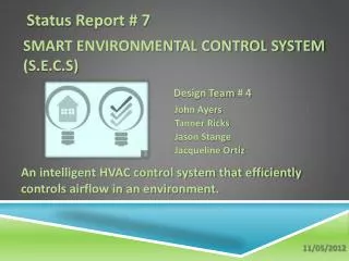
Canopy • Side opening – oil filled strut to assist with opening • Bird strike capable (4 pound bird up to 270 kts) – windscreen & front transparency • Components: • Canopy frame • Windscreen • Front transparency • Rear transparency • Weather seal • Pressure seal Canopy Weather Seal (Pressure Seal not visible) Rear Transparency Front Transparency Windscreen Canopy Frame
5 Over-Centering Hooks & Guide Pins Canopy • Latching mechanism • Continuous drive rod (internally down canopy frame) • Attached to external & internal canopy handle • Drives 5 over-centering hooks & guide pins in to canopy rail to secure canopy • Mechanical Canopy Lock Indicators • 2 in each cockpit behind internal canopy handle • Green tab showing to indicate canopy is latched • No tab indicates canopy is not latched • Electrical Sensing System • 4 microswitches– 3 in latching mechanism / 1 on canopy sill (forward edge) • Activate a CANOPYwarning to indicate the canopy is not latched • Canopy operation procedures in Section 1 of NATOPS (Know them!!) Hook Guide Pin Mechanical Lock Indicator Canopy Rail
External Canopy Handle Canopy • External Canopy Handle • Must push Unlock Button to move out of CLOSE position • One handle located by front cockpit only • Internal Canopy Open & Lift Handle • Both cockpits • Rotate forward to latch canopy • Lift Lock Release Lever to rotate handle aft to unlatch canopy • Canopy Lock Release Handle • On outboard, right side of both cockpits • Pulled to release over-center lock and allow canopy to close Canopy Lock Release Handle Internal Canopy Open & Lift Handle Lock Release Lever
Canopy Operation • **Always ensure canopy rail is cleared and CFS Pin Storage Box is closed prior to canopy movement** • To close canopy from inside: • Pull canopy lock release handle (right side) • Grab canopy frame (left hand) & pull canopy past the center position then release canopy lock release handle • Pull canopy (left hand on canopy frame & then use elbow) down to canopy sill (ensure internal handle is full aft) • Rotate internal handle forward slowly until resistance is felt then reverse direction until pressure is relieved then continue to rotate handle forward to LATCHED position • Once closed • Momentarily lift lock release lever (check canopy warning illuminate and handle does not rotate aft) • Gently rotate handle aft to feel canopy lock • Verify mechanical green indicators are visible • To open canopy from inside: • Raise and hold lock release lever (aft of internal handle) with right hand • Rotate canopy handle aft to UNLOCK position with left hand • Use canopy handle (left hand) and a hand on top of canopy (right hand) to open canopy Closing from Inside (not full procedure)
Canopy Canopy Fracturing System (CFS) External CFS Handle • 2 modes of operation • Automatic – activates during ejection sequence (via CFS attach bolt assembly) • Manual– Internal CFS handle in each cockpit/External CFS handle on each side of aircraft • Internal CFS Handle • Located in each cockpit behind PCL • Rotate 90° then pull up to activate CFS • Handle activates respective transparency • External CFS Handle • On both sides of aircraft near wing trailing edge • Pull handle out on a 10 foot lanyard to activate • Activates the fracturing system for both transparencies • Explosives • Front transparency • Uses flexible linear shaped charge (FLSC) • Thicker transparency • Cracks into two pieces • Rear transparency • Uses mild detonating cord (MDC) • Thinner transparency • Only centerline diamond pattern detonates on ejection • Handle detonates both periphery and diamond pattern Internal CFS Handle (Front Cockpit) MDC FLSC
Canopy Canopy Fracturing System (CFS) • Operation • Pulling a CFS handle activates piezoelectric crystals (no electricity required) • Piezoelectric crystals produce electric charge to fire flash lamps • Flash lamps excite a laser rod that sends energy to front/rear cockpit optical detonators (also called donor assembly) • Optical detonators fires a plunger into CFS acceptor assembly (on canopy) • Acceptor assembly fires mild detonating cords that lead to activation of the FSLS or MDC Optical Detonators (Donor Assembly) Front Cockpit Plungers Rear Cockpit Plungers Lead Detonating Cord Acceptor Assemblies CFS Attach Bolt & Assembly (for Ejection)
Canopy (Limitations) • Do not open canopy on ground when surface winds exceed 40 kts • When aircraft parked in direct sunlight in temperatures of 35°C (95°F) and above: * * * * Most common scenarios
Anti-G • G-suit hose connector in each cockpit • aft, left side of panel • Hose mechanically connected to system • Quick disconnect coupling (for egress) • Test Button • Aft of G-suit connection • Pushing down depresses weighted rod in system and allows bleed air to the suit G-suit Hose G-suit Connection (Front Cockpit) G-suit Test Button
DEFOG RAM AIR FLOW BLEED AIR INFLOW CANOPY AUTO Rt Side P3 Port HI HI DEFOG (ON): -Opens BLFC & BPV -Opens BLFC & SOV to “HI” -Turns on Air Conditioner -Up to 40 sec to close Bleed Air Inflow: HI: Full open NORM: Half-way open OFF: Closed Air Conditioning NORM NORM COLD HOT MANUAL OFF OFF OFF FOOT Inflow Valve (Bi-Level Flow Control & Shutoff Valve) • Engine-driven, vapor-cycle system • Components • Evaporator Modules • Utilizes Evap-Blower fan to pull cockpit air across cooling coils • Cooling coils exchange latent heat in the air (changes liquid refrigerant to vapor) • Discharges air through one eye-ball-type outlet and 2 outlets on the glare shield • AC Compressor • Belt driven from prop shaft • Moves refrigerant (vapor) to the Condenser/Blower • Condenser/Blower • Returns vapor to a high pressure liquid • Blower expels heat out 2 exhaust vents on bottom of aircraft Defog Valve (Bi-Level Flow Control & Bypass Valve) Cowl Vent Canopy Seal/Anti-G Electric Shutoff Valve Blower Heat Exchanger WOW Fresh Air Valve Water Separator (Closes @ 8,000’) Heat Exchanger Bypass Valve 60-90 F Firewall Shutoff Valve 7 psi Safety Valve Heating Sys Ejector (Increases defog volume) Air Conditioning Discharge Temp Sensor Canopy Seal Valve Defog Defog Butterfly Valve Foot Warmer Evap Blwr DUCT TEMP 300 F Compressor Blower Intake Temp Sensor Air Conditioning System G-Suit Cockpit Temp Control Sensor Butterfly Valve Defog Foot Warmer Evap Blwr G-Suit Cabin Temp Sensor Blower Exhaust
DEFOG RAM AIR FLOW BLEED AIR INFLOW CANOPY AUTO Rt Side P3 Port HI HI DEFOG (ON): -Opens BLFC & BPV -Opens BLFC & SOV to “HI” -Turns on Air Conditioner -Up to 40 sec to close Bleed Air Inflow: HI: Full open NORM: Half-way open OFF: Closed Air Conditioning NORM NORM COLD HOT MANUAL OFF OFF OFF FOOT Inflow Valve (Bi-Level Flow Control & Shutoff Valve) Defog Valve (Bi-Level Flow Control & Bypass Valve) • Controls • Environmental Control Panel (front cockpit) • Rear cockpit only has EVAP BLWR rheostat • AIR COND switch turns air conditioning system ON or OFF (engages compressor) • EVAP BLWR rheostat controls the fan and volume of air blowing out air conditioning ports • Operation • Cockpit cooling air available: • Engine running • Generator is on line • Generator bus is powered • Either AIR COND or DEFOG switch is ON • Bi-level pressure switch interrupts power to compressor if high or low system pressure (auto resets) • Evaporator blowers are on anytime AVIONICS MASTER switch is ON Cowl Vent Canopy Seal/Anti-G Electric Shutoff Valve Blower Heat Exchanger WOW Fresh Air Valve Water Separator (Closes @ 8,000’) Heat Exchanger Bypass Valve 60-90 F Firewall Shutoff Valve 7 psi Safety Valve Heating Sys Ejector (Increases defog volume) Temp Sensor Canopy Seal Valve Defog Defog Butterfly Valve Foot Warmer Evap Blwr DUCT TEMP 300 F Bleed Air Inflow Switch Temp Sensor G-Suit Cockpit Temp Control Sensor Butterfly Valve Evaporator Blower Switch Defog Foot Warmer Evap Blwr G-Suit Cabin Temp Sensor
RAM/DUMP DEFOG RAM AIR FLOW BLEED AIR INFLOW CANOPY AUTO Rt Side P3 Port HI HI DEFOG (ON): -Opens BLFC & BPV -Opens BLFC & SOV to “HI” -Turns on Air Conditioner -Up to 40 sec to close Bleed Air Inflow: HI: Full open NORM: Half-way open OFF: Closed Pressurization NORM COLD NORM DUMP HOT MANUAL OFF OFF OFF NORM FOOT Inflow Valve (Bi-Level Flow Control & Shutoff Valve) PRESSURIZATION Defog Valve (Bi-Level Flow Control & Bypass Valve) • Requires structurally reinforced cockpit (pressure floor/firewall/aft bulkhead/canopy) • Pressurization Switch • On Environmental Control Panel (front cockpit only) • Guarded 3-position switch (guarded to NORM) • Must lift guard to select DUMP or RAM/DUMP • In all switch positions, bleed air will continue to enter cockpit • NORM • System works automatically • Normal pressurization schedule followed • DUMP • Removes power from dump solenoid opening control valve (pressurization is lost) • RAM/DUMP • Removes power from dump solenoid opening control valve (pressurization is lost) • Opens fresh air valve • Closes defog valve (if open) Cowl Vent Canopy Seal/Anti-G Electric Shutoff Valve Blower Heat Exchanger WOW Fresh Air Valve Water Separator (Closes @ 8,000’) Heat Exchanger Bypass Valve 60-90 F Firewall Shutoff Valve 7 psi Safety Valve Heating Sys Ejector (Increases defog volume) Temp Sensor Canopy Seal Valve Defog Defog Butterfly Valve Foot Warmer Evap Blwr DUCT TEMP 300 F Pressurization Switch Temp Sensor G-Suit Cockpit Temp Control Sensor Butterfly Valve Defog Foot Warmer Evap Blwr G-Suit Cabin Temp Sensor Dump Solenoid Pressurization: RAM/DUMP: Opens Control Valve & Fresh Air Valve / Dumps press DUMP: Dumps press NORM: Follows normal press sched
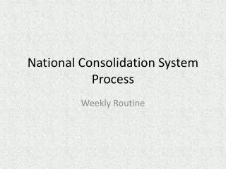
RAM/DUMP DEFOG RAM AIR FLOW BLEED AIR INFLOW CANOPY AUTO Rt Side P3 Port HI HI DEFOG (ON): -Opens BLFC & BPV -Opens BLFC & SOV to “HI” -Turns on Air Conditioner -Up to 40 sec to close Bleed Air Inflow: HI: Full open NORM: Half-way open OFF: Closed Pressurization NORM COLD NORM DUMP HOT MANUAL OFF OFF OFF NORM FOOT Inflow Valve (Bi-Level Flow Control & Shutoff Valve) PRESSURIZATION Defog Valve (Bi-Level Flow Control & Bypass Valve) • Pressurization Schedule • Cabin altitude follows aircraft altitude as aircraft climbs from sea level • At approx. 8,000 ft PA, pressurization begins holding cockpit altitude to 8,000 ft • Cockpit altitude remains at 8,000 ft PA until a differential pressure (ΔP) of 3.6±0.2 is reached at 18,069 ft • Cockpit altitude then climbs as aircraft climbs to keep a ΔP of 3.6±0.2 • Cockpit altitude is 16,600 ft PA at service ceiling of 31,000 ft • **Notify maintenance if reading other than 3.6±0.2 are encountered at or above 18,069 ft** • Indicators • Cockpit altitude & ΔP readout on EICAS display • Information sent to EICAS by EDM • A CKPT ALT caution illuminates & CKPALT readout on EICAS display turns amber if cabin altitude above 19,000 ft • A CKPT PX warning illuminates & ΔP readout on EICAS display turns red if cockpit ΔP exceeds 3.9 to 4.0 psi Cowl Vent Canopy Seal/Anti-G Electric Shutoff Valve Blower Heat Exchanger WOW Fresh Air Valve Water Separator (Closes @ 8,000’) Heat Exchanger Bypass Valve 60-90 F Firewall Shutoff Valve 7 psi Safety Valve Heating Sys Ejector (Increases defog volume) Temp Sensor Canopy Seal Valve Defog Defog Butterfly Valve Foot Warmer Evap Blwr DUCT TEMP 300 F Temp Sensor G-Suit CKPT ALT Cockpit Temp Control Sensor (Cabin: 19,000’) Acft AltCabin Alt 31,000’ 16,600’ 18,069’ 8,000’ (3.6 +/-0.2 ΔP) 8,000’ 8,000’ (Pressurization Begins) Butterfly Valve Defog Foot Warmer Cockpit Altitude Evap Blwr G-Suit Cabin Temp Sensor Dump Solenoid Differential Pressure CKPT PX Pressurization: RAM/DUMP: Opens Control Valve & Fresh Air Valve / Dumps press DUMP: Dumps press NORM: Follows normal press sched (Delta P: 3.9 - 4.0)
RAM/DUMP DEFOG RAM AIR FLOW BLEED AIR INFLOW CANOPY AUTO Rt Side P3 Port HI HI DEFOG (ON): -Opens BLFC & BPV -Opens BLFC & SOV to “HI” -Turns on Air Conditioner -Up to 40 sec to close Bleed Air Inflow: HI: Full open NORM: Half-way open OFF: Closed Pressurization (System Operation) NORM COLD NORM DUMP HOT MANUAL OFF OFF OFF NORM FOOT Inflow Valve (Bi-Level Flow Control & Shutoff Valve) PRESSURIZATION Defog Valve (Bi-Level Flow Control & Bypass Valve) • ΔP Regulator • Monitors pressure differential between cockpit and outside • Sends signal to Safety Valve if ΔP exceeds 4.0 psi • Safety Valve • Controlled by ΔP Regulator • Opens to relieve overpressure in cockpit Cowl Vent Canopy Seal/Anti-G Electric Shutoff Valve Blower Heat Exchanger WOW Fresh Air Valve Water Separator (Closes @ 8,000’) Looking up through right E-Bay Heat Exchanger Bypass Valve 60-90 F Firewall Shutoff Valve ΔP Regulator 7 psi Safety Valve Heating Sys Ejector (Increases defog volume) Temp Sensor Canopy Seal Valve Safety Valve (inside duct/ not shown Defog Defog Butterfly Valve Foot Warmer Evap Blwr DUCT TEMP 300 F Temp Sensor G-Suit Fwd CKPT ALT Cockpit Temp Control Sensor (Cabin: 19,000’) Acft AltCabin Alt 31,000’ 16,600’ 18,069’ 8,000’ (3.6 +/-0.2 ΔP) 8,000’ 8,000’ (Pressurization Begins) Cockpit Aft Bulkhead Butterfly Valve Defog Foot Warmer Evap Blwr G-Suit Cabin Temp Sensor Left Side Access Plate Dump Solenoid Delta-P Regulator Safety Outflow Valve CKPT PX Pressurization: RAM/DUMP: Opens Control Valve & Fresh Air Valve / Dumps press DUMP: Dumps press NORM: Follows normal press sched (Delta P: 3.9 - 4.0)
RAM/DUMP DEFOG RAM AIR FLOW BLEED AIR INFLOW CANOPY AUTO Rt Side P3 Port HI HI DEFOG (ON): -Opens BLFC & BPV -Opens BLFC & SOV to “HI” -Turns on Air Conditioner -Up to 40 sec to close Bleed Air Inflow: HI: Full open NORM: Half-way open OFF: Closed Pressurization (System Operation) NORM NORM COLD DUMP HOT MANUAL OFF OFF OFF NORM FOOT Inflow Valve (Bi-Level Flow Control & Shutoff Valve) PRESSURIZATION Defog Valve (Bi-Level Flow Control & Bypass Valve) • Dump Solenoid • Must be powered to allow Control Valve Regulator to work • Anytime solenoid is de-energized, control valve will open (unpress) • WOW switch de-energizes and prevents pressurizing • Airborne with WOW, energized and allows pressurization at 8,000 ft • Control Valve Regulator • Monitors cockpit pressure • Adjusts position of Pressurization Control Valve to maintain pressurization schedule • Pressurization Control Valve • Opens & closes as directed by Control Valve Regulator Cowl Vent Canopy Seal/Anti-G Electric Shutoff Valve Blower Heat Exchanger WOW Fresh Air Valve Water Separator (Closes @ 8,000’) Heat Exchanger Bypass Valve 60-90 F Firewall Shutoff Valve 7 psi Safety Valve Heating Sys Ejector (Increases defog volume) Temp Sensor Canopy Seal Valve Defog Defog Butterfly Valve Foot Warmer Looking up through left E-Bay Evap Blwr DUCT TEMP 300 F Temp Sensor G-Suit CKPT ALT Dump Solenoid Cockpit Temp Control Sensor (Cabin: 19,000’) Acft AltCabin Alt 31,000’ 16,600’ 18,069’ 8,000’ (3.6 +/-0.2 ΔP) 8,000’ 8,000’ (Pressurization Begins) Aircraft Right Side Butterfly Valve Control Valve Regulator (inside duct/ not shown) Defog Foot Warmer Evap Blwr G-Suit Cabin Temp Sensor Cockpit Aft Bulkhead WOW Dump Solenoid Control Valve Regulator Delta-P Regulator Safety Outflow Valve Control Valve Fwd (Delta-P: 3.6 +/-0.2) CKPT PX Pressurization Control Valve (inside duct/ not shown) Pressurization: RAM/DUMP: Opens Control Valve & Fresh Air Valve / Dumps press DUMP: Dumps press NORM: Follows normal press sched (Delta P: 3.9 - 4.0)
RAM/DUMP DEFOG RAM AIR FLOW BLEED AIR INFLOW CANOPY AUTO Rt Side P3 Port HI HI DEFOG (ON): -Opens BLFC & BPV -Opens BLFC & SOV to “HI” -Turns on Air Conditioner -Up to 40 sec to close Bleed Air Inflow: HI: Full open NORM: Half-way open OFF: Closed NORM COLD NORM DUMP HOT MANUAL OFF OFF OFF NORM FOOT Inflow Valve (Bi-Level Flow Control & Shutoff Valve) PRESSURIZATION Defog Valve (Bi-Level Flow Control & Bypass Valve) Conclusion Cowl Vent Canopy Seal/Anti-G Electric Shutoff Valve Blower Heat Exchanger WOW Fresh Air Valve • Identified components and described operation of heating/defog/ventilation/air conditioning systems • Described Environmental Control Panel switches and operation • Identified operations limits of heating/defog/ventilation/air conditioning systems • Identified canopy components and described normal and emergency operations • Identified anti-G components and described normal operations of system Water Separator (Closes @ 8,000’) Heat Exchanger Bypass Valve 60-90 F Firewall Shutoff Valve 7 psi Safety Valve Heating Sys Ejector (Increases defog volume) Temp Sensor Canopy Seal Valve Defog Defog Butterfly Valve Foot Warmer Evap Blwr DUCT TEMP 300 F Temp Sensor G-Suit CKPT ALT Cockpit Temp Control Sensor (Cabin: 19,000’) Acft AltCabin Alt 31,000’ 16,600’ 18,069’ 8,000’ (3.6 +/-0.2 ΔP) 8,000’ 8,000’ (Pressurization Begins) Butterfly Valve Defog Foot Warmer Abnormal ECS Scenarios located in Procedures Section/EPs Evap Blwr G-Suit Cabin Temp Sensor WOW Dump Solenoid Control Valve Regulator Delta-P Regulator Safety Outflow Valve Control Valve (Delta-P: 3.6 +/-0.2) CKPT PX Pressurization: RAM/DUMP: Opens Control Valve & Fresh Air Valve / Dumps press DUMP: Dumps press NORM: Follows normal press sched (Delta P: 3.9 - 4.0)