Download
1 / 10
100 likes | 230 Views
1. Aims 2. Physics Simulations 3. Cooling+Mechanics 4. MAPS Simulations 5. Beam Test Results 6. Radiation Hardness 7. Summary. R&D on MAPS Pixel Detectors for ILC. presented *) by Robert Klanner University of Hamburg. *) V.Adler, T.Haas, U.Kötz, B.Löhr, W.Zeuner (DESY)

E N D
1. Aims 2. Physics Simulations 3. Cooling+Mechanics 4. MAPS Simulations 5. Beam Test Results 6. Radiation Hardness 7. Summary R&D on MAPS Pixel Detectors for ILC presented*) by Robert Klanner University of Hamburg *) V.Adler, T.Haas, U.Kötz, B.Löhr, W.Zeuner (DESY) D.Contarato, E.Fretwurst (Hamburg) M.Adamus, J.Ciborowski, P.Luzniak (Warsaw and Lodz) R. Klanner Univ. Hamburg
Aims 1. Aims • ILC needs best possible vertex detector MAPS one possible option(ILC requirements: <5mm resolution, 50mm 2-particle separation, minimum multiple scattering (< 0.1%X0), fast readout tuned to ILC bunch-pattern, on-line data sparsification, radiation hard ~1010.1MeV-n-equ./cm2/year (500 Gy/year), ~2.1012e(10MeV)/cm2year) • MAPS sensors from IReS-Strasbourg (MIMOSA) • Hamburg + Warsaw group work on: • physics simulation and layout optimization • design of mechanical structure • cooling and power cycling • MAPS sensor simulation • measurements with sources (55Fe) and in DESY test-beam (electrons up to 6GeV) • radiation hardness for electrons (+photons, neutrons and hadrons) • learn, how to use MAPS in a realistic environment R. Klanner Univ. Hamburg
Layout and Physics Simulations 2. Physics Simulations • adapt fast simulation tool SGV to vertex detector, • interface to the standard heavy flavour identification package ZVDTP • compare results to full simulation using BRAHMS significant differences: Brahms-SGV S.Hillert, Oxford purity no. jets b-tag probability efficiency Neural network output for the b-tag; comparison of full and fast simulation for light q- and b-jets Purity versus efficiency for tagging b- and c-jets for the full and the fast simulation R. Klanner Univ. Hamburg
- - Layout and Physics Simulations Layout optimization: test reaction: e+e- Z0+Higgs ( cc and bb) + SM-background ECM=500 GeV and L=500 fb-1 accuracy of Higgs BR determination • 5 (4) layers (15/26/37/48/60mm): • impact of missing inner layer (5 4 layers) • position resolution of sensors (2 10mm) • effect of multiple scattering (50 300 mm Si) inner layer important for charm – in particular if Dx >> 2 mm Dx = 2 mm 5o mm Si 40 40 D BR/BR[%] D BR/BR[%] 20 20 2 5 10 300 150 50 R. Klanner Univ. Hamburg
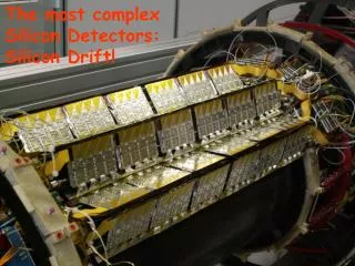
Cooling and Mechanical Support 3. Cooling and Mechanical Design • mechanical CAD design of detector • cooling test set-up with evaporative C3F8 with 600 mm capillaries heat evaporation 80% gas system working (-12°C) with dummy 30 mm glass plates with evaporated Al-resistors to simulate power detailed FE heat transfers simu- lations to understand the experi- mental results need 1kW cooling for vertex detect. if no power cycling ( O(10 W) if cycled ?) ! • pulsed powering test of MIMOSA-5 (in preparation) R. Klanner Univ. Hamburg
MAPS Simulations-1 4. MAPS 3-D Simulations • understand functioning, optimum parameters + interpret measurements • technological parameters sensor design • simulate radiation damage - use program: ISE-TCAD(3x3 pixels) R. Klanner Univ. Hamburg
410e MAPS Simulations-2 charge collection time ~80ns strong diffusion in epi-layer significant contribution to signal from substrate fast recombination in substr. expected PH vs pixel agrees ~ with test beam results simulation now applied to sub-m technology + radiation effects 790e 3x3 575e 2x2 central pixel 100 ns results from test beam measurements charge collection vs time [s] (MIMOSA 5 simulation) epi-layer substrate charge collection vs thickness epi-layer [mm] R. Klanner Univ. Hamburg
790 20 Beam Test Results-1 5.Tests in DESYII Beam - bremsstrahlungs/conversion beam with Ee up to 6 GeV - reference telescope with 2mm reso- lution (multiple scattering is larger!) - cooling down to -15°C (needed for irradiated detectors) Results:20e noise - 790e signal (9pix) R. Klanner Univ. Hamburg
Beam Test Results-2 Noise vs temperature (Noise2∝Ileak=a+b.T2exp(-Egap/2kT)) – signal independent of T Efficiency depends on cut on S/Nseed and (due to multiple scattering) on distance predicted - reconstructed e > 99% 20e 10e Charge sharing between pixels agrees ~ with simulations(p.7) Spatial resolution << 10mm multiple scattering !!! R. Klanner Univ. Hamburg
Radiation Hardness and Summary 6. Radiation Hardness Expectations at ILC (for 3 years of nominal running): - “non-ionizing” radiation: 3.1010 neq/cm2 MIMOSA9chip irradiated with 10+12n/cm2 test beam: S/N ~ 18, e > 99% - “ionizing” radiation: 5.4.1012e(10MeV)/cm2 MIMOSA5 and MIMOSA9chips irradiated at Darmstadt with 1013e(9.4MeV)/cm2 test beam (MIMOSA9): S/N ~ 20, e > 99% - results preliminary and data still under analysis 7. Summary: some work done, and lots of interesting work ahead 55Fe response MIMOSA5 irradiated by 1013e to 55Fe-source (PH pixel with max.signal) R. Klanner Univ. Hamburg