Download
1 / 6
150 likes | 512 Views
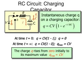
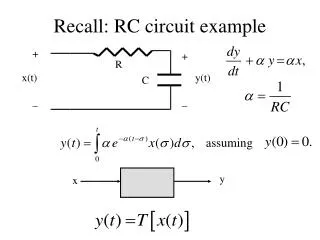
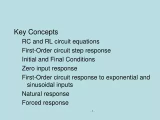
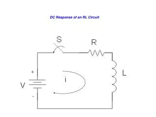
Step Response of an RC Circuit. + v C (t) -. i(t). Close the switch at t = 0 Write KCL at the top node Allow for the possibility of an initial voltage V 0. Step Response of a RC Circuit. + v C (t) -. i(t). Write KCL at the top node. Look at the results.

E N D
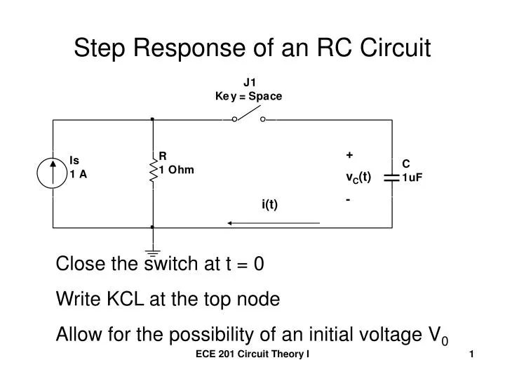
Step Response of an RC Circuit + vC(t) - i(t) Close the switch at t = 0 Write KCL at the top node Allow for the possibility of an initial voltage V0 ECE 201 Circuit Theory I
Step Response of a RC Circuit + vC(t) - i(t) • Write KCL at the top node ECE 201 Circuit Theory I
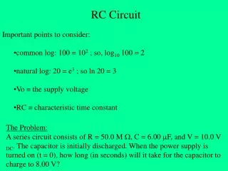
Look at the results Initial Voltage @ Capacitor = V0 Final Voltage @ Capacitor = IsR Time Constant = RC ECE 201 Circuit Theory I
Results (continued) i(t) + V0 - V0/R ECE 201 Circuit Theory I
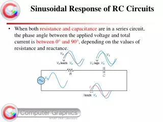
Plot the current ECE 201 Circuit Theory I
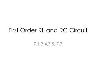
Plot the capacitor voltage ECE 201 Circuit Theory I